Cesky: |
PicoVGA - VGA/TV display on Raspberry Pico
Version 1.0, June 2021
(c) Miroslav Nemecek

Download PicoVGA library (copy on ulozto.cz)
Video with sample programs: https://www.youtube.com/watch?v=wX1IPa3Q0LU (copy on ulozto.cz)
PicoVGA on Github: https://github.com/Panda381/PicoVGA

Contents
The PicoVGA library allows output from the Raspberry Pico to a VGA monitor or PAL/NTSC TV, with a focus on ease of use in technical and gaming applications. It provides 4 graphic overlay layers with transparency, nearly 30 frame buffer formats that can be freely combined with each other, making do with limited RAM memory size. The limitation of output to 8 bits also contributes to RAM saving.
The RP2040 processor contains 264 KB of RAM. This is not much for higher resolution image output and therefore RAM needs to be very sparing. In technical practice and for retro games (the processor does not have the power for more advanced games), 8-bit graphics output in R3G3B2 format (i.e. red 3 bits, green 3 bits and blue 2 bits) is fully sufficient. Output in 16 or 24 bits is not meaningful in normal practice, as the Raspberry Pico does not have enough memory or power to provide such large amounts of data in areas other than short demos. Using the dithering technique, interesting display results can be achieved even with 8-bit output.
To try out the library, in the simplest case, just take 8 resistors, connect them to outputs GP0 to GP7 and RGB connector of VGA or SCART TV, connect HSync (CSync) to GP8, headphones to GP19 and load the demo program via USB (the programs are ready compiled in the library package). If keyboard control is needed, run a console program such as begPutty, but most programs work without a keyboard.
Update note: You can use Wayne Venables' project to compile PicoVGA for Pico W in Linux. You can also find there the addition of the VSYNC signal to the library (look for VGA_GPIO_VSYNC in vga.cpp). github.com/codaris/picovga-cmake
License terms: The PicoVGA library source code and the PicoVGA library sample programs are freely available for further use and modifications. This does not apply to certain graphics and sounds (such as the sounds in Pac-Man) and scene definitions in Sokoban, as these are subject to third party copyrights and may be subject to different distribution terms.
Here is an example of output to TV in interlaced mode, with reduction from VGA connector to SCART TV connector. The VGA/SCART reduction contains only a simple pin connection of the connectors, possibly 1 more resistor for blanking signal.

Image generation on the Raspberry Pico is a matter of processor utilization limits and other processor activities must be subordinated to it. When using the PicoVGA library, there are several principles to keep in mind:
The library always runs on the second core of the processor and the program on the first core. Rendering the image can completely overload the CPU core and is usually unusable for other use. The separation of core functions also has the advantage that the cores do not affect each other and there is no need for mutual locking. The first core simply uses write to the frame buffers and the second core displays the contents of the frame buffers without any communication between them. This makes the overall work easier and faster.
If the second core is not very busy (e.g. when displaying 8-bit graphics that are simply transferred using DMA transfer), it can also be used for the main program work. However, some limitations should be taken into account - the program in the second core should not use interrupts (it would interfere with the rendering function), the interpolation unit should be used with caution (the rendering function does not save its state) and it must not disable interrupts.
An important rule is that all data to be accessed by the PicoVGA library must be stored in the RAM memory. External flash memory is slow and cannot be used for rendering functions. For example, if a flash image is to be displayed, it must first be copied to a buffer in RAM, and then a pointer to the RAM copy of the image will be passed to the rendering function. If a pointer to the image in flash were passed to it, slow access to flash would cause video dropouts. In addition to images, this also applies to fonts and tile patterns, for example.
The limited rendering speed must be taken into account when scheduling screen layout. Some modes render very fast (e.g. 8-bit graphics are just transferred from the frame buffer using DMA) and some modes are very rendering intensive - e.g. rendering sprites in slow mode. When using demanding rendering, some video lines may not render fast enough in the required time and the video image will break (drop out of sync). In such cases, it is necessary to use another mode, or to reduce the rendered area (add other modes, faster ones - e.g. add tile controls on the sides of the screen), reduce the screen resolution or increase the CPU clock speed. Video lines are rendered separately and therefore it is always just content on one video line about, video lines do not affect each other. For example, you can test the speed of sprite rendering by placing all the sprites horizontally next to each other (the most challenging case) and check if the video synchronization fails.
Care must also be taken when using DMA transfer. DMA is used to transfer data to the PIO. Although the transfer uses a FIFO cache, using a different DMA channel may cause the render DMA channel to be delayed and thus cause the video to drop out. A DMA overload can occur, for example, when a large block of data in RAM is transferred quickly. However, the biggest load is the DMA transfer of data from flash memory. In this case, the DMA channel waits for data to be read from flash via QSPI and thus blocks the DMA render channel.
The CPU clock frequency must also be subordinated to the image generator. Before initializing the video node, the library calculates the required system clock frequency so that the timing matches the requirements and the processor speed is sufficient for the required image resolution. It is a good idea to initially print out the calculated clock frequency for checking on the console. It is possible to prohibit the library from changing the system clock, or to prescribe only a certain range, in which case some modes may be unreachable (or the video image may break up).
Image buffers must be aligned to 4 bytes (32-bit CPU word) and image segments must be horizontally aligned to 4 pixels - this refers to the horizontal position of the segment, its width, alignment (wrapx) and offset (offx). Alignment does not apply to the vertical direction. This restriction is necessary because the image information is transferred to the PIO controller using a 32-bit DMA transfer, and this must be aligned to a 32-bit word. One 32-bit word contains 4 pixels (1 pixel has 8 bits), so the horizontal data in the image must also be aligned to 4 pixels. So you cannot do fine horizontal scrolling of the image in 1 pixel increments (the restriction does not apply to vertical scrolling), but only in 4 pixel increments. The exception to this is slow sprites, which are software rendered to the video line and can therefore be scrolled in 1 pixel increments. Similarly, the restriction does not apply to software rendering to framebuffer (e.g. rendering an image to video memory can be done to any coordinate).
The PicoVGA library is ready for simplified compilation in a Windows environment, requiring only the installation of the ARM-GCC compiler. Compilation for Linux is not ready, I leave this area to someone more familiar with the Linux environment. ;-)
You need the ARM-GCC compiler for compilation. You can download it here:
Currently, this would be the version gcc-arm-none-eabi-10-2020-q4-major-win32.exe. I recommend installing the compiler to the C:\ARM10 folder and disabling the option to add the path to the PATH when installing. The different versions of the compiler are not always completely interchangeable and it is therefore practical to have multiple versions installed (C:\ARM9, C:\ARM8, etc.) and to add the path to the version of the compiler used inside the command file. The compilation files in PicoVGA are also prepared in this way. If you want to change the path to the compiler folder, you can find it in the _c1.bat and _boot2\c.bat compilation files. If you don't want to use multiple versions of the compiler, leave the installation in the default folder and leave the option to add the path to the PATH enabled, the compilation will work correctly as well.
Unzip the PicoVGA library into any folder. Anywhere you want to work. ... And that completes the installation. :-)
For more recommendations on how to easily use RaspberryPicoSDK libraries in Windows, see the description "Easy Compilation of Raspberry Pico under Windows": https://www.breatharian.eu/hw/rasppico/index_en.html .
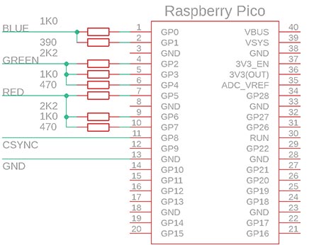
I don't present here the overall circuit I used, because the library was created as part of a retro gaming computer with Raspberry Pico and is still under development. Here is a simplified wiring diagram of the VGA monitor output (with added audio PWM output):

The synchronization output is in the format of the CSYNC synchronization mix (composite synchro, HSYNC + VSYNC). Computer monitors support CSYNC mixed sync. The signal is fed to the HSYNC input (also referred to as CSYNC). An audio output is fed to the VSYNC pin of the VGA connector, for case of output to the TV. The VGA monitor has an input impedance of 75 ohms on this pin, this causes the audio signal to be attenuated and ignored by the VGA monitor and not considered as vertical sync. When the audio connector is inserted, the output to the VGA monitor is disconnected and the audio signal is output to the outside (e.g. to audio headphones).
The TV is connected to the VGA output via a reduction that simply connects the pins of the VGA connector to the corresponding pins of the SCART connector. In this case, the audio signal fed to the VGA connector is also used. Thus, it is not necessary for the device to include a special connector for the TV. The 5V voltage from pin 9 is used as the control voltage for the SCART connector - pin 16 of the SCART connector (Blanking) is connected via a 100 ohm resistor and pin 8 (Switch) is connected directly.
The keyboard connection is not draw here. All sample programs are set up so that program control can be used via the console on the USB virtual port. Simply connect the Pico to the PC via the USB cable used for programming, and run a console program (e.g. begPutty) that connects to the USB virtual COM port. For a more detailed description of the connection, see the SDK description.
The easiest way to incorporate the PicoVGA library into a project is to use an existing sample project. For maximum simplicity, all source files are included in the projects. While it takes a little longer to compile, it does not require adjustments to the selection and order of the files to be compiled, thus simplifying the resulting work.
When incorporating a library into an existing project, the _picovga folder containing the PicoVGA library source files must be taken over. The global.h file contains the *.h header files to be included in the project (_picovga/define.h, etc.). The compiled files to be added can be found in the Makefile.inc file. Firstly, the assembler file group "ASM picovga" and secondly the C source code "C picovga".
The PicoVGA library requires the vga.pio file, compiled by the pioasm.exe compiler into the vga.pio.h file. In the current project folder, it looks for the file include.h, which lists all header files, including vga.pio.h.
It also searches the current folder for the vga_config.h file. This contains the PicoVGA library settings, such as the size of the render buffers. You usually do not need to pay attention to the vga_config.h file. You usually have to interfere with it in the following cases:
All demo examples in PicoVGA are ready compiled (compiled file is always named program.uf2) - compiled for VGA monitor and USB console keyboard. Just load them into Pico by running e.bat (="Export"). If you want to change anything in the code, you can get the new compilation by running c.bat (="Compile"). In FAR, just press c<Enter>. To clean up compilation, run d.bat (="Delete"). This deletes all intermediate files and leaves only the resulting compiled file program.uf2.
During the compilation process, it is ensured that when editing *.c, *.asm and *.cpp files, only the changed files are compiled, not the whole project. Thus, a complete compilation after each code change is not necessary. However, there is not provided compilation depending on the *.h header files, this should be kept in mind. So normally compile quickly using c.bat and only after more significant changes in *.h or if there is suspicious behaviour, first delete the old compilation using d.bat and then do full compilation.
In the PicoVGA base folder you will also find the files c_all.bat and d_all.bat - these are used to bulk compile or clean up the compilation of all demo programs.
In the Makefile file, located next to each project, you will find the project settings. As a rule, you can get by with adding additional *.c source files to the CSRC variable and *.cpp files to the SRC variable. If you add *.h header files to the project, add them to the src\include.h file. Enter link include.h at the beginning of each *.c and *.cpp file.
You can load a compiled program into Pico either by dragging and dropping it with the mouse or by using the e.bat command file. For this purpose it is useful to name the disk uniformly, e.g. R: (=Raspberry). The renaming is done in the computer administration - via This computer / Manage. Or edit the disk name in the _e1.bat file.
In PicoVGA you will find the following folders:
_boot2 - Bootloaders of the 2nd level.
_exe - elf2uf2 program to export the compiled program from elf2 format to uf2 format, and pioasm, a program compiler for PIO. The programs are ready for 64-bit Windows. For a 32-bit system, use the libraries from the 32bit folder.
_picovga - PicoVGA library, along with supporting programs
_sdk - Pico SDK library files. The structure is simplified compared to the original SDK. All *.c files are in one folder and all *.h files are in the include folder.
_tinyusb - TinyUSB library for USB port handling.
_tools - utilities to handle compilation from the MinGW library, such as the "make.exe" program, etc.
_www - the content of this web page with description.
Other folders contain demo examples.
The video mode can be initialized either simply by the Video() function or in more detail by the following functions.
Video(u8 dev, u8 res, u8 form, u8* buf, const void* buf2) ... Simplified initialization of the video mode. See vga_vmode.h for a description of the function and parameters. This function incorporates the following functions listed here below. It supports only 1 display segment and has a limited repertoire of formats and resolutions, but may be sufficient in some cases. The function only needs to pass a pointer to the frame buffer, which is a u8 array of sufficient size for the image data. The function uses the library's default global structures (Cfg, Vmode, Canvas), otherwise the program can use the default global structures arbitrarily. When using the Video function, the following initialization functions are not needed.
multicore_launch_core1(VgaCore) ... The first function that should be called in the project starts the second processor core with the PicoVGA library.
void VgaCfg(const sVgaCfg* cfg, sVmode* vmode) ... Prepare the structure for setting up the video mode. The sVgaCfg structure (description in vga_vmode.h) contains the required properties of the video mode - the required display resolution, the required minimum processor frequency and the required timing of the sVideo* signal (also in vga_vmode.h), possibly also the required overlay mode. You can first call the VgaCfgDef function, which presets the structure to the default parameters - 640x480 resolution, VGA display, processor frequency 120 to 270 MHz. The VgaCfg function prepares the sVmode descriptor structure, which is later passed to the init function. At this point no operations are taking place yet, only the necessary settings are being calculated. After the calculation, some items of the sVmode structure can be adjusted. In the library there are global structures Cfg and Vmode that can be used for the function. The required screen resolution and signal timing are two independent properties. For timing, you are limited only by the number of video lines of the image, but otherwise you can set any screen resolution within them. For example, for PAL and NTSC video, you can set a VGA video resolution. To make the program versatile so that it can be run on both a VGA monitor and a TV, use a VGA resolution of 640x480 or 320x240 (or 512x400 and 256x192, due to RAM limitations). When changing the display, just select VGA/PAL or NTSC timing, the resolution does not change for the program.
set_sys_clock_pll(Vmode.vco*1000, Vmode.pd1, Vmode.pd2) ... Set the system clock. The VgaCfg function has calculated the required processor frequency, the calculated values are passed to the system clock setting function. The required frequency limit can be specified with the VgaCfg function.
ScreenClear(pScreen) ... Clear the display and initialize the display structure. At a minimum, this function should be called before initializing the videmode. It initializes the display content descriptor structure pointed to by pScreen (usually the default structure Screen of the library) by setting the number of segments to 0. The screen will be black until we fill it with content descriptors (see below).
VgaInitReq(&Vmode) ... Initialize the video mode. This function passes the library a pointer to the format descriptor generated by the VgaCfg function. This function does not actually initialize the video mode, it just passes the pointer to the library in the 2nd processor core and then waits for confirmation that the initialization is complete. If the video mode needs to be changed (this refers to changing the timing of the video signal and changing the type of overlay layers), it is necessary to first stop the video generation by calling the VgaInitReq function with the NULL parameter, and only then call the function with the new video mode setting.
If the 2nd core is not too busy generating the video, it can be passed a request to perform the function. This does not affect the video generation, it may just happen that the requested function runs slowly when the generator is heavily loaded. The function cannot use interrupts, cannot disable interrupts, and may be restricted from using the hardware interpolator (video interrupt does not save its state).
Core1Exec(void (*fnc)()) ... execution of the function by core 1.
Bool Core1Busy() ... test if core 1 is busy executing the function.
Core1Wait() ... wait for core 1 to exit the function.
When displaying screen image, the default pointer is pScreen for the library. It points to the sScreen structure that describes the contents of the display. The Raspberry Pico has a limited RAM size and cannot accommodate a high resolution image. Therefore, the image must be composed of smaller segments to minimize the memory-intensive parts.
Note: The following descriptions of the image format only apply to the base image layer 0. It is the only one that can contain segments in different formats. Overlay layers 1 through 3 are independent of the base layer format, sharing only the total screen area with the base layer but using their own image format.
ScreenClear(sScreen* s) ... Resets the display handler structures, clearing the display. This function should always be called at the start of creating a new screen content definition (segment initialization).
sStrip* ScreenAddStrip(sScreen* s, int height) ... This function adds a new horizontal bar of the specified number of video lines to the end of the screen definition. The maximum number of stripes is specified by the STRIPMAX constant (8 by default) in the vga_config.h file. Without added segments, the bar is empty (black).
sSegm* ScreenAddSegm(sStrip* strip, int width) ... This function adds a new image segment of the specified width to the end of the strip. The segment will contain one image format. For the vast majority of formats, the width must be a multiple of 4 (a multiple of 4 pixels).
The following are functions for setting the specific image segment format. The definition of the sSegm segment can be found in vga_screen.h. There are some parameters that are not controlled by functions: offx specifies the horizontal offset of the image (horizontal scrolling). For the vast majority of formats, horizontal scrolling must be in multiples of 4. The offs parameter specifies vertical scrolling. This can be done gently over video lines. The wrapx parameter specifies the alignment after which the buffer contents are repeated. It is thus possible, for example, to display an image in tile format or, conversely, to create a virtual screen larger than the display. This parameter must again be a multiple of 4. Similarly, the wrapy parameter specifies the vertical repetition of the image. The dbly parameter doubles the vertical lines. This can be used for an image with low horizontal resolution.
The 'wb' function parameter specifies the line length in bytes. The 'data' parameter is a pointer to a frame buffer with graphic data. The 'font' parameter, for text functions, is a pointer to the font. A font is a 1-bit mono image with 256 characters per line. Each character is 8 pixels wide, so the line length is 2048 pixels (256 bytes). Vertically, the font can be any size - the height of the font is given by the 'fontheight' parameter. A list of available fonts can be found in the _picovga\font folder.
ScreenSegmColor(sSegm* segm, u32 col1, u32 col2) ... The segment will be filled with color (GF_COLOR). Parameters col1 and col2 represent the 4 pixel colors for even and odd lines. The segment can thus contain a colored raster instead of a solid color. The MULTICOL macro can be used to merge the 4 pixel colors.
ScreenSegmGrad1(sSegm* segm, const void* data, int wb) ... The segment will be filled with a color gradient (GF_GRAD1). The gradient is 1 line of 8-bit pixels. The gradient can be scrolled horizontally with the offx parameter.
ScreenSegmGrad2(sSegm* segm, const void* data, int wb) ... Gradient with 2 lines, even and odd (GF_GRAD2).
ScreenSegmGraph8(sSegm* segm, const void* data, int wb) ... 8-bit graphics 256 colors (GF_GRAPH8). Each pixel is 1 byte. This mode is one of the fastest, the data is simply sent from the frame buffer to the PIO controller using a DMA transfer. However, it is also one of the most memory intensive. Really, the memory can hold a maximum image resolution of 512x400 pixels (EGA video mode).
ScreenSegmGraph4(sSegm* segm, const void* data, const void* trans, int wb) ... 4-bit palette graphics 16 colors (GF_GRAPH4). There are 2 pixels in 1 byte (the first pixel is in the higher 4 bits of the byte). The function requires a palette translation table, which is generated by the following function:
GenPal16Trans(u16* trans, const u8* pal) ... Generate a palette translation table for the ScreenSegmGraph4 function. The translation table is 256 entries of 16 bits, so it takes 512 bytes in memory. The table is used during display for internal purposes, must be aligned to 4 bytes, and must be available for the entire time the segment is displayed. The input to the function is the palette table, which is 16 color entries of 1 byte.
ScreenSegmGraph2(sSegm* segm, const void* data, const void* trans, int wb) ... 2-bit palette graphics 4 colors (GF_GRAPH2). There are 4 pixels in 1 byte (first pixel in the highest 2 bits). The function requires a palette translation table, which is generated by the following function:
GenPal4Trans(u32* trans, const u8* pal) ... Generate a palette translation table for the ScreenSegmGraph2 function. The translation table is 256 entries with a size of 32 bits, so it takes 1024 bytes in memory. The table is used during display for internal purposes, must be aligned to 4 bytes, and must be available for the entire time the segment is displayed. The input to the function is the palette table, which is 4 color entries of 1 byte.
ScreenSegmGraph1(sSegm* segm, const void* data, u8 bg, u8 fg, int wb) ... 1-bit mono graphics 2 colors (GF_GRAPH1). There are 8 pixels in 1 byte (first pixel in the highest bit). The function requires background color bg and foreground color fg.
ScreenSegmMText(sSegm* segm, const void* data, const void* font, u16 fontheight, u8 bg, u8 fg, int wb) ... Mono text (GF_MTEXT). For mono text, the foreground and background color is valid for the entire segment. In the display memory there are single characters, 1 byte is one character
ScreenSegmAText(sSegm* segm, const void* data, const void* font, u16 fontheight, const void* pal, int wb) ... Attribute text (GF_ATEXT). In attribute text, each character is a pair of bytes. The first byte is the ASCII value of the character, the second byte is the color attribute. The higher 4 bits of the attribute represent the background color, the lower 4 bits of the attribute represent the foreground color. The colors are translated from a palette table of 16 colors.
ScreenSegmFText(sSegm* segm, const void* data, const void* font, u16 fontheight, u8 bg, int wb) ... Text with foreground color (GF_FTEXT). In text with foreground, each character is represented by a pair of bytes. The first byte is ASCII value of the character, the second byte is foreground color. The background color is common, specified by the 'bg' parameter. It is worth noting that the library's default fonts include an inverted lower half of the font in the upper half (bit 7 set) - this can provide a character with an optional background color.
ScreenSegmCText(sSegm* segm, const void* data, const void* font, u16 fontheight, int wb) ... Text with color (GF_CTEXT). For text with color, each character occupies 3 bytes. The first byte is the ASCII value of the character, the second byte is the background color, and the third byte is the foreground color.
ScreenSegmGText(sSegm* segm, const void* data, const void* font, u8 fontheight, u8 bg, const void* grad, int wb) ... Text with gradient (GF_GTEXT). In this mode, each character is represented by 1 byte in memory and the background color is specified by the 'bg' parameter, similar to the mono text. Instead of the foreground color, there is a parameter 'grad', which is a pointer to a color gradient of length equal to the graphic length of the line of text (e.g. for 40 characters, the gradient is 320 bytes). The foreground color for each pixel of the character is taken from the gradient table.
ScreenSegmDText(sSegm* segm, const void* data, const void* font, u8 fontheight, u8 bg, const void* grad, int wb) ... Double gradient text (GF_DTEXT). The function is identical to the previous function, except that each character pixel is generated as 2 image pixels. Thus, the character has twice the width. It is the only text mode that allows displaying characters with double width. The color gradient works similarly here, but 1 byte of the gradient represents 1 pixel of the character (as in the previous function), not 1 pixel displayed. Thus a line of 40 characters again requires a gradient of 320 bytes.
ScreenSegmTile(sSegm* segm, const void* data, const void* tiles, int w, int h, int wb) ... Tiles in column (GF_TILE). Tiles are image segments of the specified size (tile width and height are 'w' and 'h'). The tile patterns are arranged in a single image. In this case, into a column of width 1 tile. The 'tiles' parameter is a pointer to the image of the tile column. The 'data' parameter is a pointer to an array of bytes, where each byte represents number of displayed tile. Thus, there can be a maximum of 256 tiles. The 'wb' parameter refers to the length of the row of the index array (not the length of the tile image). The width of a tile must be a multiple of 4, at least 8. Tiles allow efficient display of image information by allowing the image to repeat. Thus, high image resolution can be achieved with low memory requirements.
ScreenSegmTile2(sSegm* segm, const void* data, const void* tiles, int w, int h, int tilewb, int wb) ... Tiles in a row (GF_TILE2). This function is an alternative to the previous function, except that the tile patterns are arranged in a single row in the image. This may be more convenient when creating a tile image, however, you must additionally specify the parameter 'tilewb' representing the line length of the tile image. Usually tilewb = number of tiles * tile width.
ScreenSegmLevel(sSegm* segm, const void* data, u8 bg, u8 fg, u8 zero) ... Level display segment (GF_LEVEL). This segment is used to display graphs. The input is an array of 'data' bytes of length corresponding to the width of the array in pixels. The byte value represents the height of the graph at the given X coordinate. The display will show a foreground or background color depending on whether the displayed pixel lies above or below the value from the data array. The 'zero' parameter specifies the height of the reference zero. Zero does not imply negative numbers in the data, the numbers are still given as unsigned (with zero at the bottom). Starting from reference zero, the background and foreground colour is swapped. This results in the graph looking visually symmetrical around the reference zero. You can see the appearance of the segment in the Oscilloscope sample program (lower curve).
ScreenSegmLevelGrad(sSegm* segm, const void* data, const void* sample1, const void* sample2) ... Level display segment with gradient (GF_LEVELGRAD). This segment is used to display graphs, similar to the previous function. It differs in that the color is given as a vertical gradient with a height corresponding to the height of the segment. If a pixel lies below the data value, the color from the first gradient is used. Otherwise, the second gradient is used. An example use case can be seen in the Level Meter sample program, to display the spectrum.
ScreenSegmOscil(sSegm* segm, const void* data, u8 bg, u8 fg, int pixh) ... Oscilloscope waveform display segment (GF_OSCIL). The segment is similar in function to the level display segment. It differs in that the curve is displayed as a line of 'pixh' pixel thickness. This function is already more demanding and may not be able to service the full width of the image.
ScreenSegmOscLine(sSegm* segm, const void* data, u8 bg, u8 fg) ... Oscilloscope continuous waveform segment (GF_OSCLINE). The curve is displayed as a continuous line with a thickness of 1 pixel. This mode is already very demanding to render and is therefore accelerated by halving the horizontal resolution (renders points 2 pixels wide).
ScreenSegmPlane2(sSegm* segm, const void* data, int plane, const void* trans, int wb) ... 2-bit palette graphics 4 colors in 2 planes (GF_PLANE2). The mode is functionally similar to the 2-bit color graphics mode, but the individual pixel bits are stored in 2 separate color planes. This mode is similar to the CGA graphics mode of PC computers. The individual planes correspond to two separate monochrome graphics modes. Each byte of the plane contains 8 pixels (the first pixel in the highest bit). The parameter 'plane' is the relative offset of the second plane from the first plane, given by the parameter 'data'. The function requires a palette translation table, which is generated by the following function:
GenPal4Plane(u32* trans, const u8* pal) ... Generate a palette translation table for the ScreenSegmPlane2 function. The translation table is 256 entries of 32 bits, so it takes 1024 bytes in memory. The table is used during display for internal purposes, must be aligned to 4 bytes, and must be available for the entire time the segment is displayed. The input to the function is the palette table, which is 4 color entries of 1 byte.
Although there is no program in the PicoVGA library utilities that prepares an image in 2-plane mode, there is an internal function Plane2Conv that converts a 4-color image to 2-plane mode. Thus, the image is attached to the program as a 4-color image, and the conversion function is used to prepare a copy in RAM.
ScreenSegmAttrib8(sSegm* segm, const void* data, const void* attr, const u8* pal, int wb) ... Graphical mode with attributes (GF_ATTRIB8). This mode is known from ZX Spectrum computers. The 'data' parameter is a pointer to the pixel data. This corresponds to the monochrome display mode, where each bit distinguishes whether foreground or background color is used. The 'attr' parameter is a pointer to an array of color attributes. The color attribute is a byte, where the lower 4 bits represent the foreground color and the upper 4 bits the background color. The attribute is converted to a colored pixel using the palette table 'pal', which is an array of 16 bytes of colors. Each attribute specifies the foreground and background colors for a group of 8 x 8 pixels. Thus, for every 8 bytes of pixels, there is 1 byte of color attributes. The 'wb' parameter here specifies the line width in bytes for both the pixel array and the attribute array. The difference is that the address in the attributes array is not incremented after each line, but after 8 lines.
Although there is no program in the PicoVGA library utilities that prepares an image in attribute mode, there is an internal function Attr8Conv that converts an image in 16 colors to attribute mode. Thus, the image is attached to the program as a 16-color image, and the conversion function is used to prepare a copy in RAM.
ScreenSegmProgress(sSegm* segm, const void* data, const void* sample1, const void* sample2) ... Progress indicator (GF_PROGRESS). Progress indicator is a horizontal indicator. The parameter 'data' is an array of bytes of length corresponding to the height of the segment. The byte value indicates the line length in multiples of 4 pixels. Thus, a value of 0 to 255 represents an indicator length of 0 to 1020 pixels. For the first part of the indicator (< data) the colour gradient 'sample1' is displayed, for the second part (>= data) 'sample2' is displayed.
ScreenSegmGraph8Mat(sSegm* segm, const void* data, const int* mat, u16 xbits, u16 ybits) ... 8-bit graphics with 2D matrix transformation. This segment displays an 8-bit image with transformations - rotate, scale, skew and shift. The image must have width and height as a power of 2. The width and height of the image are specified using the xbits and ybits parameters as the number of bits of the dimension. For example, for a 512 x 256 pixel image, xbits = 9, ybits = 8. The 'mat' parameter is a pointer to an array of 6 integer transformation matrix parameters - see the Transformation matrix section. The segment does not support parameters for image shifting and wrapping, they must be left at default values.
ScreenSegmGraph8Persp(sSegm* segm, const void* data, const int* mat, u16 xbits, u16 ybits, u16 horiz) ... v
ScreenSegmTilePersp(sSegm* segm, const u8* map, const u8* tiles, const int* mat, u8 mapwbits, u8 maphbits, u8 tilebits, s8 horizon) ... Tile graphics with 3D perspective. Similar to the previous function, it is used to display terrain with 3D projection. It uses tile definition instead of 8-bit graphics. This allows the display of very large terrains. The 'map' parameter is a pointer to a map of tiles - tile indices 0 to 255. The width and height of the map must be powers of 2 and are specified as the number of mapwbits and maphbits. Tiles must have a square dimension, which must also be a power of 2. The tile dimension is specified by the tilebits parameter as the number of dimension bits. The 'tiles' parameter is a pointer to an image with a pattern of tiles arranged in 1 column of tiles. The 'horizon' parameter specifies the horizon offset over the segment boundary / 4. A positive number represents the horizon offset, a negative number will invert the perspective (can be used to display the sky). A zero value turns off the perspective - in this case the function is similar to the function for displaying an image with a transformation matrix (the array of tiles can be rotated, skewed, etc).
ScreenSegmTilePersp15(sSegm* segm, const u8* map, const u8* tiles, const int* mat, u8 mapwbits, u8 maphbits, u8 tilebits, s8 horizon) ... Similar function, but the pixels are rendered 1.5 pixels wide. This function can be used if the previous function does not keep up with the rendering speed.
ScreenSegmTilePersp2(sSegm* segm, const u8* map, const u8* tiles, const int* mat, u8 mapwbits, u8 maphbits, u8 tilebits, s8 horizon) ... Similar function, but the pixels are rendered 2 pixels wide. This function can be used if the previous function does not keep up with the rendering speed.
ScreenSegmTilePersp3(sSegm* segm, const u8* map, const u8* tiles, const int* mat, u8 mapwbits, u8 maphbits, u8 tilebits, s8 horizon) ... Similar function, but the pixels are rendered 3 pixels wide. This function can be used if the previous function does not keep up with the rendering speed.
ScreenSegmTilePersp4(sSegm* segm, const u8* map, const u8* tiles, const int* mat, u8 mapwbits, u8 maphbits, u8 tilebits, s8 horizon) ... Similar function, but the pixels are rendered 4 pixels wide. This function can be used if the previous function does not keep up with the rendering speed.
The display of the image by the PicoVGA library is performed by the PIO processor controller. PIO0 is used. The other controller, PIO1, is unused and can be used for other purposes. PIO0 contains a 4 state machine, SM0 to SM3. All PIO0 state machines use a common program of 32 instructions. Each state machine serves 1 overlay layer. SM0 services base layer 0, along with servicing the synchronization signal. The base layer service program consists of 15 instructions, starting at offset 17. This part of the program is immutable and is always used. The other 3 layers, 1 to 3, SM1 to SM3, use the other part of the program memory, 17 instructions starting at address 0. This part may change, depending on the mode of the overlay layers. All 3 overlay layers use a common program and must therefore operate in the same display mode. Some overlay modes use the same program and can be shared - see the table below for details.
Note: Only base layer 0 can contain segments in different formats. Overlay layers 1 to 3 are independent of the base layer format, sharing only the total display area with the base layer, but using their own image format, for which only the coordinates and dimensions are specified.
Overlay layers can use one of the following programs:
LAYERPROG_BASE ... is the name of the base layer 0 program. Cannot be used for overlay layers. Using the parameter for an overlay layer means that the layer is inactive (not using the program).
LAYERPROG_KEY ... layer with key color. The specified color is replaced by transparency.
LAYERPROG_BLACK ... transparency with black color. Black is replaced by transparency. Compared to the previous mode, the advantage is less demanding on processor speed.
LAYERPROG_WHITE ... transparency with white colour. It is faster like the previous function and is suitable for use where black needs to be preserved but white can be omitted. When preparing the image, the image is not copied from Flash to RAM with the memcpy function, but the CopyWhiteImg function is used. The function ensures that the pixels of the copied image are incremented by 1. This changes the white color (with a value of 255) to black (with a value of 0). From this point on, the image is treated as if it had transparency with black - e.g. the black color is specified for the sprite rendering function. Only when the image enters the program in PIO0, the program makes the pixel transparent as in the case of black, but at the same time decrements the pixel value. This reverts the colors back to the original value, the black color becomes black and the white color has been used as transparency.
LAYERPROG_MONO ... This programme includes 2 sub-programmes. The first is the display of a monochrome image. For each bit of image data, either the selected image color is displayed or the corresponding pixel is transparent. This mode is used in the Oscilloscope example to display a grid across the oscilloscope screen. The second subroutine is to display a color image without transparency. The color pixels are displayed as they are, with no transparency option, but the dimensions of the image rectangle and its coordinate on the display can be defined. Thus, a sort of analogy of a single rectangular sprite without transparency.
LAYERPROG_RLE ... RLE compression mode. RLE compression is not a universally valid format. It means that the data contains segment length information. In this case, the image data of PicoVGA library contain directly instructions for the PIO program. More specifically, the image data is interleaved with the jump addresses inside the program. The image is prepared using the RaspPicoRle program and is strongly coupled to the layer program used. If, for example, the instructions in the program were shifted, the RLE compression format would stop working. This is also why the program for base layer 0 is placed at the end of the program memory and the overlay layer programs at the beginning - to reduce the chance that changes in the program will change the location of the program in memory, at which point RLE compression would stop working. After modifying the RLE program in PIO, the conversion program must also be updated.
The desired mode of each overlay layer is specified in the video mode definition using the VgaCfg function. The layer mode is used to derive the program and function used to operate the layer rendering. Multiple layer modes can share the same program type. Layer modes have different state machine timing requirements. The configuration function takes this into account and adjusts the processor frequency accordingly.
Modes of overlay layers:
*WHITE modes using white transparent color require image preparation using CopyWhiteImg as specified for LAYERPROG_WHITE.
LAYERMODE_BASE ... Indicates base layer mode 0. Cannot be used for an overlay layer, but is used to indicate an inactive disabled overlay layer.
LAYERMODE_KEY ... The layer with the specified key color.
LAYERMODE_BLACK ... Layer with black key color.
LAYERMODE_WHITE ... Layer with white key color.
LAYERMODE_MONO ... Monochromatic image.
LAYERMODE_COLOR ... Colour image (without transparency).
LAYERMODE_RLE ... Image with RLE compression.
LAYERMODE_SPRITEKEY ... Sprays with the specified key color.
LAYERMODE_SPRITEBLACK ... Sprays with black key color.
LAYERMODE_SPRITEWHITE ... Sprays with white key color.
LAYERMODE_FASTSPRITEKEY ... Fast sprites with the specified key colour.
LAYERMODE_FASTSPRITEBLACK ... Fast sprites with black key colour.
LAYERMODE_FASTSPRITEWHITE ... Fast sprites with white key colour.
LAYERMODE_PERSPKEY ... Image with transformation matrix with specified key color.
LAYERMODE_PERSPBLACK ... Image with transformation matrix with black key color.
LAYERMODE_PERSPWHITE ... Image with transformation matrix with white key color.
LAYERMODE_PERSP2KEY ... Image with transformation matrix with specified key color and doubled width.
LAYERMODE_PERSP2BLACK ... Image with transformation matrix with black key color and doubled width.
LAYERMODE_PERSP2WHITE ... Image with transformation matrix with white key color and doubled width.
Shared overlay modes:
Layer modes can only be combined together if they use the same program. CPP is the minimum required number of SMx clock cycles per pixel.
| PROG_BASE | PROG_KEY | PROG_BLACK | PROG_WHITE | PROG_MONO | PROG_RLE | CPP | |
| LAYERMODE_BASE | x | 2 | |||||
| LAYERMODE_KEY | x | 6 | |||||
| LAYERMODE_BLACK | x | 4 | |||||
| LAYERMODE_WHITE | x | 4 | |||||
| LAYERMODE_MONO | x | 4 | |||||
| LAYERMODE_COLOR | x | 2 | |||||
| LAYERMODE_RLE | x | 3 | |||||
| LAYERMODE_SPRITEKEY | x | 6 | |||||
| LAYERMODE_SPRITEBLACK | x | 4 | |||||
| LAYERMODE_SPRITEWHITE | x | 4 | |||||
| LAYERMODE_FASTSPRITEKEY | x | 6 | |||||
| LAYERMODE_FASTSPRITEBLACK | x | 4 | |||||
| LAYERMODE_FASTSPRITEWHITE | x | 4 | |||||
| LAYERMODE_PERSPKEY | x | 6 | |||||
| LAYERMODE_PERSPBLACK | x | 4 | |||||
| LAYERMODE_PERSPWHITE | x | 4 | |||||
| LAYERMODE_PERSP2KEY | x | 6 | |||||
| LAYERMODE_PERSP2BLACK | x | 4 | |||||
| LAYERMODE_PERSP2WHITE | x | 4 |
Selection of write planes
By default, the image is output from the layers to all output pins. This can be changed by redefining the LayerFirstPin and LayerNumPin fields (in vga_layer.cpp). It is possible to specify for each layer separately which output pins will be written to. This can create a kind of pseudo-transparency. For example, one layer will render curves in red, another layer in green, and the colors will blend independently. When redefining the pins, however, you must take into account that the offset of the pin mapping will shift. The output will always start from the lowest bits of the pixel.
Configure overlay layers
The first step for setting up the overlay layer is to specify the layer mode for the VgaCfg initialization function. The function detects the required program and the required timing. It does not check if the correct layer modes are combined together.
The second step is to initialize the layer descriptor - the sLayer structure in the LayerScreen field. It is convenient to use the initialization function for this:
LayerSetup(u8 inx, const u8* img, const sVmode* vmode, u16 w, u16 h, u8 col = 0, const void* par = NULL) ... The 'inx' parameter contains the layer number 1..3, 'img' is a pointer to the image data, 'vmode' is a pointer to the prepared Vmode structure, 'w' is the width of the panel, 'h' is the height of the panel, 'col' is the key color. For both *BLACK and *WHITE modes, specify COL_BLACK (or 0). 'par' is an additional parameter. The function sets the dimensions of the image and its address. The coordinates are cleared. The position of the image on the screen can be set by the LayetSetX and LayerSetY functions. The coordinates do not depend on the graphic modes of the base layer and refer to the upper left corner of the active screen area.
After initialization, the layer remains disabled. Layer visibility must be turned on by calling the LayerOn function.
In the case of the transformation matrix mode (LAYERMODE_PERSP*), this function is used instead:
LayerPerspSetup(u8 inx, const u8* img, const sVmode* vmode, u16 w, u16 h, u8 xbits, u8 ybits, s8 horiz, const int* mat, u8 col = 0) ... In contrast to the previous function, the dimensions of the source image in number of bits (the image dimensions must be a power of 2), the height of the horizon/4 (for a negative value the floor turns into a ceiling, for zero the perspective transformation is not applied) and the pointer to the transformation matrix in integer form are also specified.
In case of the mode with sprites, this function is used:
LayerSpriteSetup(u8 inx, sSprite** sprite, u16 spritenum, const sVmode* vmode, s16 x, s16 y, u16 w, u16 h, u8 col = 0) ... It differs from the previous functions by specifying the coordinate of the sprite area, the pointer to the sprite address array and the number of sprites.
Sprites can be used in overlay planes with KEY, BLACK and WHITE programs. There are two ways to use the sprites:
When using sprites, the first step will be to specify the LAYERMODE_*SPRITE* layer mode for the VgaCfg initialization function.
The second step will be to build an array of sprite pattern line starts and lengths using the SpritePrepLines function. The function will be passed a pointer to the image of each sprite (only 8-bit sprites are supported), the image dimensions, the pointers to the array of origin and line lengths (the array dimensions correspond to the height of the sprite), and the key transparency color. The function searches for line starts and line ends and writes them into the fields. The 'fast' parameter specifies whether the tables are generated for fast sprites, in which case the line starts and lengths are divided by 4. For slow sprites, the sprite width must be limited to 255 pixels.
SpritePrepLines(const u8* img, u8* x0, u8* w0, u16 w, u16 h, u16 wb, u8 col, Bool fast)
The third step is to build a list of sprites and initialize the sprites - especially the pointer to the image, the dimensions and coordinates of the sprites. The sprite list is an array of pointers to the sprite. Each sprite can only be in the list once, but multiple sprite can share the same sprite image and the same array of line starts and lengths. Slow sprites can have coordinates outside the allowed range (they will be cropped), but for fast sprites I recommend not to exceed the horizontal limits of the screen, the cropping of the image is not yet properly tuned and the program might crash.
While the sprites don't have a parameter to turn them off, they can be turned off by setting the Y coordinate out off screen. During rendering, visible sprites are searched for by the Y coordinate, an invalid Y coordinate will ensure that the sprite is safely disabled.
Fast sprites require sorting the list by the X coordinate. This is done by the SortSprite function, which is passed a pointer to the list of sprites and the number of sprites in the list. This function should be called whenever you change the X coordinate of the sprite. Transient conditions (e.g. momentary mis-overlapping of sprites) do not matter, they are just short-term optical errors, they do not compromise the program. The function sorts using the bubble method, so it is quite slow, but so far it does not seem to harm anything (there are not many sprays).
SortSprite(sSprite** list, int num)
The last step is the initialization of the layer with the sprite. The function was described in the previous chapter.
LayerSpriteSetup(u8 inx, sSprite** sprite, u16 spritenum, const sVmode* vmode, s16 x, s16 y, u16 w, u16 h, u8 col = 0)
The next step is to turn on layer visibility with LayerOn and control the sprites by changing their X and Y coordinates and changing their img images.
Canvas is a drawing board. It is a support library for working with graphical surfaces and images (see the canvas.h file in the _picovga\util folder). The sCanvas structure is a set of parameters that describe the graphical surface, for use in drawing functions. A graphical surface can be either a graphical frame buffer or an image, even in Flash.
To draw in a graphical surface, first attach a canvas to it as a definition describing the structure of the area. Likewise, if you want to draw an image to the surface, first create a canvas for the image with its parameters. The parameters are a pointer to the image data, the image dimensions, and the format. The drawing area can be a graphic area with a depth of 1, 2, 4, 8 bits or with attributes. In the case of drawing an image to a canvas, the source and target canvas must have the same format. In the case of transformation matrices, only an 8-bit graphic format can be drawn.
Note: In PicoVGA, a default canvas 'Canvas' is available. A graphic frame buffer is automatically attached to it when initialized with the Video function. Otherwise, it can be used arbitrarily in the program.
DrawRect(sCanvas* canvas, int x, int y, int w, int h, u8 col) ... drawing a rectangle.
DrawFrame(sCanvas* canvas, int x, int y, int w, int h, u8 col) ... drawing a frame of 1 pixel thickness.
DrawClear(sCanvas* canvas) ... filling the canvas with black color.
DrawPoint(sCanvas* canvas, int x, int y, u8 col) ... draw a pixel.
DrawLine(sCanvas* canvas, int x1, int y1, int x2, int y2, u8 col) ... draw a line.
DrawFillCircle(sCanvas* canvas, int x0, int y0, int r, u8 col, u8 mask=0xff) ... draw a filled circle. x0 and y0 are the coordinates of the center, r is the radius. The 'mask' specifies, using bits 0 to 7, which eighths of the circle are drawn.
DrawCircle(sCanvas* canvas, int x0, int y0, int r, u8 col, u8 mask=0xff) ... drawing a circle, parameters as in the previous function.
DrawText(sCanvas* canvas, const char* text, int x, int y, u8 col, const void* font, int fontheight=8, int scalex=1, int scaley=1) ... draw text with transparent background. scalex and scaley is the magnification scale in X and Y directions.
DrawTextBg(sCanvas* canvas, const char* text, int x, int y, u8 col, u8 bgcol, const void* font, int fontheight=8, int scalex=1, int scaley=1) ... draw text with specified background colour.
DrawImg(sCanvas* canvas, sCanvas* src, int xd, int yd, int xs, int ys, int w, int h) ... draw image (without transparency).
DrawBlit(sCanvas* canvas, sCanvas* src, int xd, int yd, int xs, int ys, int w, int h, u8 col) ... draw image, transparency specified by the key color.
DrawImgMat(sCanvas* canvas, const sCanvas* src, int x, int y, int w, int h, const class cMat2Df* m, u8 mode, u8 color) ... draw the image with transformation using the transformation matrix (rotation, etc.). More info in canvas.h.
DrawTileMap(sCanvas* canvas, const sCanvas* src, const u8* map, int mapwbits, int maphbits, int tilebits, int x, int y, int w, int h, const cMat2Df* mat, u8 horizon) ... draw a tile map with perspective.
DrawImgLine(sCanvas* canvas, sCanvas* src, int xd, int yd, int xs, int ys, int wd, int ws) ... draw the image line with interpolation.
Some rendering functions use the cMat2Df transformation matrix to define image transformation (see the mat2d.h file in the _picovga\util folder). The matrix has 6 numeric elements of float type. The transformation is prepared by setting the initial state with the Unit function and then entering the transformations one by one. Using the matrix, operations are performed on the image as if the operations were entered sequentially.
GetX ... performing the transformation for the X coordinate
GetY ... performing the transformation for the Y coordinate
Unit ... initialization of the matrix to the unit initial state
Copy ... copy of the matrix
TransX ... shift in X direction
TransY ... shift in Y direction
ScaleX ... scale in X direction
ScaleY ... scale in Y direction
RotSC ... rotation with the results of sin(a) and cos(a)
Rot ... rotation with given angle
Rot90 ... rotation by 90°
Rot180 ... rotation by 180°
Rot270 ... rotation by 270°
ShearX ... shear in X direction
ShearY ... shear in Y direction
FlipY ... vertical flip
FlipX ... horizontal flip
PrepDrawImg(int ws, int hs, int x0, int y0, int wd, int hd, float shearx, float sheary, float r, float tx, float ty) ... Preparation of the matrix for the drawing function. The order of operations is chosen as if the image is first moved to the point tx and ty, scaled, skewed, then rotated and finally moved to the target coordinates.
ExportInt(int* mat) ... Export matrix to integer array (6 elements int). After transformation, the lower 12 bits of the number contain the decimal part of the number, the upper 20 bits contain the integer part of the number. Rendering functions require this integer form of the transformation matrix.
Some display functions may be CPU speed intensive and may require overclocking to a higher speed. It should be understood that overclocking places the processor in areas where proper function is not guaranteed. The PicoVGA library allows you to control the overclocking of the processor, according to the desired video mode. The minimum and maximum processor frequency can be specified in the VgaCfg function. By default, the library allows a range of 120 to 270 MHz. However, it may happen that at higher frequencies the processor will not operate correctly and it may be necessary to lower the upper limit.
The searched processor frequency can be set with the set_sys_clock_pll function.
bool vcocalc(u32 reqkhz, u32 input, u32 vcomin, u32 vcomax, bool lowvco, u32* outkhz, u32* outvco, u16* outfbdiv, u8* outpd1, u8* outpd2) ... Function for finding the optimal setting of the PLL system clock generator. The function is used to specify the desired output frequency, the input frequency of the crystal (12 MHz in Raspberry Pico), the minimum and maximum frequency of the VCO oscillator. The output is the parameters for setting the PLL oscillator. The function returns True if it was able to find a setting for the exact value of the desired frequency. Otherwise, it searches for the setting for the closest frequency and returns False. See the overclock.h file in the _picovga\util folder.
bool FindSysClock(u32 reqkhz, u32* outkhz, u32* outvco, u16* outfbdiv, u8* outpd1, u8* outpd2) ... Find PLL generator settings with default parameters.
void __not_in_flash_func(FlashSpeedSetup)(int baud) ... Setting the interface speed for external flash.
The functions for printing text are used to output text to the text frame buffer (see the print.h file in the _picovga\util folder). Currently supported buffer formats are GF_ATEXT (text with color attribute) and GF_MTEXT (mono text).
PrintSetup(u8* buf, int bufw, int bufh, int bufwb) ... Initialization of the text printing service. The function is passed a pointer to the text frame buffer and its dimensions. If the line length in bytes is less than twice the width, the mono text format GF_MTEXT is selected, otherwise the format with the GF_ATEXT attributes is used. This function is automatically called when the video mode is initialized using the Video function.
int PrintX, PrintY ... Current print position.
u8 PrintCol ... Current print color (not applicable for mono text).
PrintClear() ... Clear the text buffer with the currently selected color.
PrintHome() ... Move the pointer to the beginning of the first line.
PrintSetPos(int x, int y) ... Setting the print pointer (column and row).
PrintAddPos(int x, int y) ... Relative shift of the print pointer.
PrintSetCol(u8 col) ... Setting the print colour. Use the PC_COLOR macro to set the color attribute.
PrintChar0(char ch) ... Printing a character into the print buffer, without taking control characters into account.
PrintChar(char ch) ... Printing a character into the print buffer, with control characters CR, LF and TAB.
PrintSpc() ... Print space character.
PrintSpcTo(int pos) ... Printing spaces up to the specified position.
PrintCharRep(char ch, int num) ... Repeated printing of the character.
PrintSpcRep(int num) ... Repeated printing of the space.
PrintText(const char* text) ... Print text.
PrintHLine(int x, int y, int w) ... Horizontal line drawing. Line drawing characters with code 17 to 31 are used for drawing, as overridden in the PicoVGA library fonts. When drawing, the line is combined with the characters already in the print buffer so that the lines are properly joined and overlapped. The function does not treat overflows outside the allowed display range.
PrintVLine(int x, int y, int h) ... Vertical line drawing. Line drawing characters with code 17 to 31 are used for drawing, as overridden in the PicoVGA library fonts. When drawing, the line is combined with the characters already in the print buffer so that the lines are properly joined and overlapped. The function does not treat overflows outside the allowed display range.
PrintFrame(int x, int y, int w, int h) ... Line frame rendering. This function uses the previous 2 drawing functions.
The PicoVGA library includes support for audio output using PWM modulation. By default, the audio output is done on the GPIO19 port - defined in the pwmsnd.h file in the _picovga\util folder. The port can be connected to directly (e.g. headphones) or better via a simple RC filter with low pass.
Audio output using PWM modulation has the advantage that 1 output pin is sufficient and the output circuitry is very simple. The disadvantages are the noise of the sound modulation frequency and the low bit depth of the sound (8 bit depth is used). Higher depth is not possible because of the limited processor frequency. This output is sufficient for most common, undemanding applications (such as retro games). For higher sound quality, another method must be used.
Note: If the system clock changes, you must reinitialize the audio output settings by calling the initialization function again.
PWMSndInit() ... Initialize the library for PWM audio output.
PlaySound(const u8* snd, int len, Bool rep = False, float speed = 1.0f) ... Audio playback. The audio must be in uncompressed PCM format, mono, 8 bits, frequency 22050 Hz. The parameters can be used to specify whether the sound will be repeated and the relative speed at which it will be played (the 'speed' parameter can be used to speed up or slow down the sound).
StopSound() ... Stops the audio playback. The output to the output pin will continue to be output (it will appear as a low noise), but the value of zero 128 will be used.
SpeedSound(float speed) ... Setting the playback speed. Used when repeatedly playing a sound to change the pitch (e.g. the sound of a car engine). A value of 1.0 represents the standard playback speed.
Bool PlayingSound() ... Tests if the audio is playing.
SetNextSound(const u8* snd, int len) ... Set the next sound to play. Used for repeated sounds to finish playing the current sound and continue with the next sound.
The cRandom library (see the rand.h file in the _picovga\util folder for details) replaces and extends the standard random number generator. A 64-bit number is used as seed, which ensures sufficient randomness of the number. The limited randomness of the standard 32-bit generator can be observed, for example, when generating terrain - it will appear as waves in the terrain. You can either use the global variable Rand and the functions belonging to it, or create another local generator cRandom. The following functions refer to the global Rand generator. It is recommended to use the RandInitSeed function when starting the program to ensure the generator is non-repeating.
u64 RandSeed() ... Returns the current state of the seed random generator. Can be used to store the state of the generator and restore it later, for a reproducible random sequence.
RandSetSeed(u64 seed) ... Randomness generator seed settings. Without the seed setting, the random generator starts with a default value of 0, which is created by zeroing the memory when the program starts.
RandInitSeed() ... Initialization of the random generator by a random number. The function uses the output of the ROSC counter. Although its output will not provide a large variety of randomness, it will ensure that the program does not start with the same randomness sequence when it is restarted. This function should always be called at the beginning after the program has been run.
u8 RandU8() ... Generate number u8 (0..255)
u16 RandU16() ... Generate number u16 (0..65535)
u32 RandU32() ... Generate number u32 (0..0xFFFFFFFF)
u64 RandU64() ... Generate number u64 (0..0xFFFFFFFFFFFFFFFF)
s8 RandS8() ... Generate number s8 (-128..+127)
s16 RandS16() ... Generate number s16 (-32 768..+-32 767)
s32 RandS32() ... Generate number s32 (-0x80000000..+0x7FFFFFFF)
s64 RandS64() ... Generate number s64 (-0x8000000000000000..+0x7FFFFFFFFFFFFFFF)
float RandFloat() ... Generate a float decimal number in the range 0 (including zero) to 1 (excluding 1).
double RandDouble() ... Generate a double decimal number in the range 0 (including zero) to 1 (excluding 1).
Generate numbers from 0 to the specified maximum (including the maximum):
u8 RandU8Max(u8 max)
u16 RandU16Max(u16 max)
u32 RandU32Max(u32 max)
u64 RandU64Max(u64 max)
s8 RandS8Max(s8 max)
s16 RandS16Max(s16 max)
s32 RandS32Max(s32 max)
s64 RandS64Max(s64 max)
float RandFloatMax(float max) ... Generate float number from 0 (including zero) to the specified maximum (excluding the maximum)
double RandDoubleMax(double max) ... Generate double number from 0 (including zero) to the specified maximum (excluding the maximum)
Generate numbers in the specified range, including boundary values (if min > max, a number outside the range is generated):
u8 RandU8MinMax(u8 min, u8 max)
u16 RandU16MinMax(u16 min, u16 max)
u32 RandU32MinMax(u32 min, u32 max)
u64 RandU64MinMax(u64 min, u64 max)
s8 RandS8MinMax(s8 min, s8 max)
s16 RandS16MinMax(s16 min, s16 max)
s32 RandS32MinMax(s32 min, s32 max)
s64 RandS64MinMax(s64 min, s64 max)
float RandFloatMinMax(float min, float max) ... Generate float number in the range min (including minimum) to max (excluding maximum)
double RandDoubleMinMax(double min, double max) ... Generate double number in the range min (including minimum) to max (excluding maximum)
float RandGaussF(float mean = 0, float sigma = 1) ... Generate a Gaussian random number float, with center 'mean' and interval width 'width'.
double RandGaussD(double mean = 0, double sigma = 1) ... Generate a Gaussian random number double, with center 'mean' and interval width 'width'.
The following functions are used to generate terrains, using coordinate-dependent wave folding. The output is a number in the range -1 to +1.
float Noise1D(int x, int seed) ... Random generator with 1 coordinate.
float Noise2D(int x, int y, int seed) ... Random generator with 2 coordinates.
float Noise3D(int x, int y, int z, int seed) ... Random generator with 3 coordinates.
float SmoothNoise1D(float x, int scale, int seed) ... Interpolated random generator with 1 dimension.
float SmoothNoise2D(float x, float y, int scale, int seed) ... Interpolated random generator with 2 dimensions.
In the _picovga\font folder you can find fonts ready to use in programs. The fonts in PicoVGA are in monochrome image format (i.e. 1 pixel is 1 bit) with 256 characters per line and a character width of 8 pixels. The total width of the image is therefore 2048 pixels (256 bytes). The height of the font can be arbitrary, but by default there are 8, 14 and 16 line fonts in the library. Fonts are exported by the RaspPicoImg utility to *.cpp source text format, and are added to the program as a byte array.
Example of font font_bold_8x8:

In the _picovga\_exe folder you can find support programs (utilities) used to convert images and sounds to the internal format used by the PicoVGA library. The files are added to the program as source code, as an array. The programs are prepared in Visual Studio 2005. They are console programs, so it should not be difficult to modify them under Linux.
In the _picovga\_exe folder you can find files with *.act palettes. You can use these files in Photoshop or Gimp when converting images to PicoVGA palettes. The most important is the pal332.act palette file. It is generated by pal332.exe (in the pal332 folder) and defines the basic 8-bit PicoVGA colors. In the pal332 folder you will also find the pal332.csv file, which contains detailed information about the colors - the color order number, the RGB value of the color, and the values of the individual components. You can view the file in Excel or Open Office, but also with any text editor. It can be useful, for example, if you read the RGB HEX value of a color in Photoshop and want to know which color index it corresponds to in PicoVGA. In that case, you look up the HEX code in the file (with the Find function) and read the corresponding color code at the beginning of the line.
When importing an image into PicoVGA colors, you convert the image to index colors, select "Custom" as the palette, and load the appropriate palette from the palette files. In some cases (photographs) it may be useful to turn on the dithering option (usually the Diffusion method with 75%), other times it is better without dithering.
Import the saved image into PicoVGA with RaspPicoImg (in the _picovga\_exe\img folder). Always save the image as a Windows BMP file, with compression turned off and reverse line order turned on (option "Flip row order"). For 8-bit graphics, use pal332.act to import the palette file and save the image as an 8-bit BMP palette file. When exporting to 4-bit graphics, use 4-bit palettes, usually pal4_PC.act (CGA palettes) or pal4_ZX.act (ZX Spectrum palettes), and save the image as a 4-bit palette image. When exporting to 2-bit graphics, use one of the 2-bit palettes palcga*.act (CGA palettes in modes 1 through 6). The BMP image does not support the 2-bit format, but you can save it as a 4-bit image, RaspPicoImg will recognize from the palettes that it is a 2-bit image and perform the appropriate conversion. When exporting to 1-bit graphics (mono), use the pal1.act palette file and save the image as a 1-bit palette file.
When converting the image to RLE compressed format, use the RaspPcoRle program in the _picovga\_exe\rle folder. The program input is a BMP image converted to 8-bit PicoVGA palettes (pal332.act palette file), saved without compression, with reverse line order enabled. The fourth program parameter is the color number to be used as transparency. The color number can be found from the HEX code (detected in Photoshop by the dropper) in the pal332.act file. If the image is not to have transparency, enter -1 instead of the transparency color.
The RaspPicoRle program is heavily dependent on the RLE PIO program. It stores instructions in code with offsets needed for the program to function. Therefore, you must always use a program from the same version as the PicoVGA library, as the format of the RLE code used may change sometime in the future.
In the snd folder you will find the RaspPicoSnd program that can be used to import sounds into PicoVGA. The imported sound must be in WAV format, uncompressed (PCM compression), 8 bit, mono, rate 22050 Hz. You can use the Cool Edit editor or the free program Audacity to edit the audio. Audacity has many sound effects, allows good manipulation of audio tracks, and has been used to prepare audio for video with samples of PicoVGA library programs.
Programs are ready for keyboard control via PC console (begPutty recommended) and virtual USB serial port. For more detailed instructions on how to connect the console, see the RaspPicoSDK article. Some games use sound - generating PWM sound via pin GP19. Games with PWM sound are marked with "(sound)".
  |
Ants - card game (sound). Two anthills compete for supremacy. The goal is to build a higher castle. Controls: J left, L right, space select card, D discard, H help, Q quit. Can be played against another player or against the computer. |
 |
Balloons - demonstration of sprite use, flying balloons (43 sprites in total). |
 |
Draw - demonstration of drawing graphic elements. For the demonstration, alternate between slow rendering and drawing at maximum speed. |
 |
Earth - rotating globe. Software spherical image transformation. |
  |
Eggs - logic game (sound). Based on the game Reversi. The goal is to get as many of your own stones as possible. One player changes stones in the direction of hen-chicken-egg, the other player in the opposite direction. Controls: L right, I up, J left, K down, H help, Q end, P 2 players, D demo, space bar to place stone, Enter ok. Can be played against another player and against the computer. |
 |
Fifteen - logic game (sound). The objective is to sort the stones in order from 1 to 15. Controls: L right, I up, J left, K down, Q new game. |
 |
Flag - fluttering flag |
 |
Ghost Racing - car racing (sound). After passing the first lap (checkpoints are required), a rival "ghost" appears, which copies your previous path. You are competing with yourself. There are a total of 2 ghost opponents in the game (the second one should appear after the second lap). The game is unfinished - I couldn't calculate the correct transformation of the opponents' image into the camera and it is now only very approximate. It's more of a half-finished game for inspiration and to demonstrate 3D terrain projection (tile areas). Controls: I gear up, K gear down, J left, L right. 5 gears can be shifted. Originally, reverse was possible, but it was rather hindering. |
  |
Gingerbread House - a fairy tale book about a gingerbread house. The program serves as a demonstration of working with images with RLE compression. Control: J previous page, L next page. |
 |
Hello World - the simplest example of using the PicoVGA library. |
 |
Hypno - a hypnotic rotating pattern. Example of matrix image transformation. |
 |
Level Meter - music spectrum indicator simulation (sound). The program uses a gradient graph level display mode. The input for the display is an array of values. There is no need to generate the indicator image programmatically and so a very fast response to change can be achieved. Random samples are used in the demo. |
 |
Life - cell life simulator (cellular automaton). Cells change at each step according to the number of neighboring cells: for 1 or less a cell dies on isolation, for 4 or more a cell dies on overpopulation, for 3 a new cell is created, for 2 there is no change. In the game, you can switch between 10 screens (slots) and transfer the image between them using the clipboard. In each slot there is a predefined definition of popular combinations. Controls: L right, I up, J left, K down, C copy to clipboard, V insert from clipboard, D clear area, space bar change cell, Enter start/stop generation, 0-9 select slot. |
 |
Lines - relaxation line pattern generator. |
  |
Mandelbrot - fractal pattern generator of Mandelbrot set. Integer mathematics is used to generate the pattern, which makes the redrawing fast. However, it must be taken into account that as the scale of the display increases, increasing accuracy in the number of digits is required. The used integer and float mathematics are sufficient up to a magnification scale of 10^5, double mathematics up to a scale of 10^10. When zooming in further, only colored lines are displayed instead of the pattern. Controls: E up, S left, D right, X down, Q scale up, A scale down, L low resolution selection 132x100, M medium resolution selection 264x200, H high resolution selection 528x400, I switch to integer math (fastest, range up to 10^-5), F switching to float math (slowest, range up to 10^-5), B switching to double math (slowest, range up to 10^-10), O decreasing the number of iteration steps, P increasing the number of iteration steps, U increasing the system clock, T decreasing the system clock, space redraw screen. |
 |
Matrix Rain - "matrix code rain" simulation. It uses text-based video mode. |
 |
Maze - the goal is to find a way out of the maze. The mazes are generated randomly programmatically. Controls: J left, I up, L right, K down, H help (showing the door). |
  |
Monoscope - video modes test. The keys 0 to 9 and A to U can be used to switch the display resolution, from 256x192 to 1280x960, for both VGA monitor and PAL/NTSC TV.For the TV, interlaced video is used for higher resolutions (such as broadcast TV), and progressive mode is used for lower resolutions (such as the outputs from 8-bit computers). Can be used to test the display on different devices. The individual test patterns are stored in the program as prepared images with RLE compression. It would be possible to modify the program to use only 1 image, which would be recomputed as needed, but would have to be compressed into RAM with RLE compression when generated, as it would not fit in RAM at full size. |
 |
Oscilloscope - demonstration of oscilloscope signal display. The program uses graph and curve display mode. The signal waveform image does not need to be generated in software, only the array of values is passed to the display, and this allows a very fast response to changing values. In the demo the samples are generated programmatically. It also serves as a demonstration of stacking image segments in different modes. The basic oscilloscope image is an 8-bit bitmap (with dithering), consisting of 4 stripes. In place of the screen, 2 elements are used to display graphs. The screen is overlaid by a transparent overlay with a grid. |
  |
Pac-Man - popular action game (sound). The game attempts to emulate the original 1980's version of the game by Namco. The logic of ghost behavior, score and level counting is followed. I would like to point out that the sounds and appearance are taken from the original game, they are covered by Namco's copyright, and therefore the game serves only as an inspirational sample. Controls: J left, I up, L right, K down, A pause. |
 |
Pi - calculating the number Pi to 4833 digits. After the calculation, the result is checked against the expected sample. |
| Pixels - random generation of colored pixels. | |
 |
Raytracing - 3D pattern generation by ray tracing method. Due to the limited color depth of PicoVGA, raster dithering ("graininess" of the image) is used in the display. |
  |
Sokoban - logic game (sound). The goal is to move the crates to the marked fields. The game contains 3000 levels from different authors, along with their solutions. Controls: L right, I up, J left, K down, H help (level solution), R restart level, Q previous level, W next level, P print info. |
 |
Spheres - random spheres generation. |
 |
Spots - random generation of spots. |
 |
Tetris - popular game, stacking blocks (sound). Control: L right, I turn, J left, K lay, A pause. |
  |
Train - logic game based on the principle of the Snake (sound). The goal is to collect all objects and pass through the gate. The game has 50 levels, along with their solutions. Controls.: L right, I up, J left, K down, H help (view solution of the level), Enter enter password, Esc back, BS delete character of password. |
 |
Twister - twisting of the textured block. It serves as an example of programmatic image deformation, using a hardware interpolator. |
 |
Water Surface - simulation of rippling water surface (sound). |
Download PicoVGA library (copy on ulozto.cz)
Miroslav Nemecek