Cesky: |
Easy Compilation of Raspberry Pico under Windows
The popular Raspberry Pico is full of elaborate documentation and quality examples, but its compilation environment is focused more on Linux, or more precisely on the Raspberry Pi. In Windows, it requires the installation of several gigabytes of supporting software and a relatively complicated method of use. If you prefer easier use, like me, I've prepared a simplified compilation environment. All you need is an ARM-GCC compiler and a ready-made package with SDK and examples (hereafter referred to as RaspPicoSDK).
You will find 73 demo examples in the RaspPicoSDK. Unlike the original, many examples are prepared for both the UART console output (eg via UART-USB adapter) and the USB console (virtual COM port). In total, there are 120 folders to compile.
1) You need the ARM-GCC compiler to compile. You can download it here:
Currently, this would be gcc-arm-none-eabi-10-2020-q4-major-win32.exe. I recommend installing the compiler in the C:\ARM10 folder and disabling the option to add the path to the PATH during installation. The individual versions of the compiler are not always completely interchangeable, so it is practical to have multiple versions installed (folders C:\ARM9, C:\ARM8, etc.) and add the path to the used version of the compiler only inside the command file. In this way, the compilation files in RaspPicoSDK are also prepared. If you want to change the path to the compiler folder, you can find it in the _c1.bat and _boot2\c.bat compilation files. If you do not want to use multiple versions of the compiler, leave the installation in the default folder and leave the option to add the path to the PATH turned on. The compilation will work properly as well.
2) Next, you need RaspPicoSDK:
download: RaspPicoSDK.zip
alternative download: ulozto.cz
Unzip RaspPicoSDK to some folder. Wherever you want to work. And that completes the installation. :-)
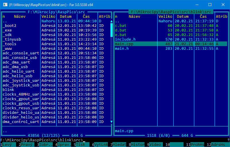
RaspPicoSDK is used on the command line, without an IDE environment. Why - because the right programmer works at the command line. :-) I highly recommend the FAR Manager (can be downloaded here https://www.farmanager.com ). It includes a Norton Commander file manager and an editor (via F4) that is well suited for writing programs for MCUs (including color syntax highlighting). It has one big advantage over other similar managers - the console window (display Ctrl+O or Ctrl+P). You see the output of the message from the compiler, so you can easily edit programs. Everything you need is immediately at hand. Searching for files by text (Alt+F7) and comparing file contents (F11, Advanced compare) also works well.
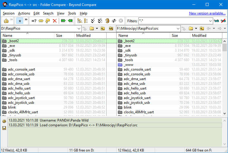
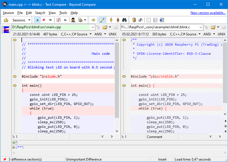
I recommend the Beyond Compare program (download https://www.scootersoftware.com/download.php ) for a really good comparison of differences in file contents and folder synchronization. When I want to compare folders or files, I place the cursor on them in the opposite FAR windows ('..' indicates "this folder"), enter the bcomp command and specify the paths to the folders as parameters using Ctrl+F. bcomp.cmd is a command file located in the C:\Windows folder, with the following contents:
@"C:\Program Files (x86)\Beyond Compare 3\BCompare.exe" %1 %2 %3 %4
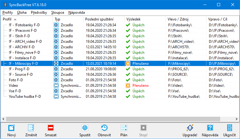
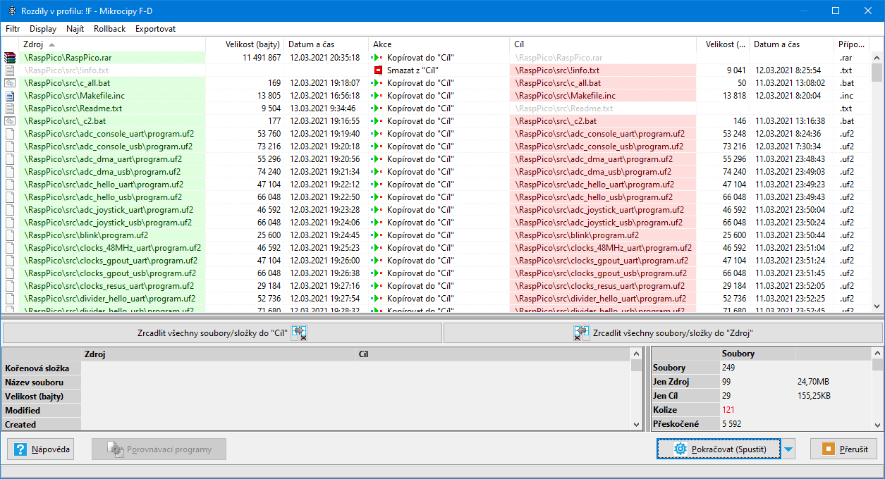
Alternatively, I recommend the SyncBackFree program (link https://www.2brightsparks.com/freeware/index.html ) to synchronize folders during archiving, I use it when backing up to external disks.
A very useful feature when working with the Raspberry Pico is a console program for communication via the serial port. I use the program begPuTTY, download begPutty.zip. Home page http://qww.cz/Ctrl-Home-and-Shift-Arrows-in-Putty-Linux.html , this is a modification of the PuTTY program https://www.chiark.greenend.org.uk/~sgtatham/putty/ . (note: To copy a text from console window to the clipboard, just select the text with the mouse)
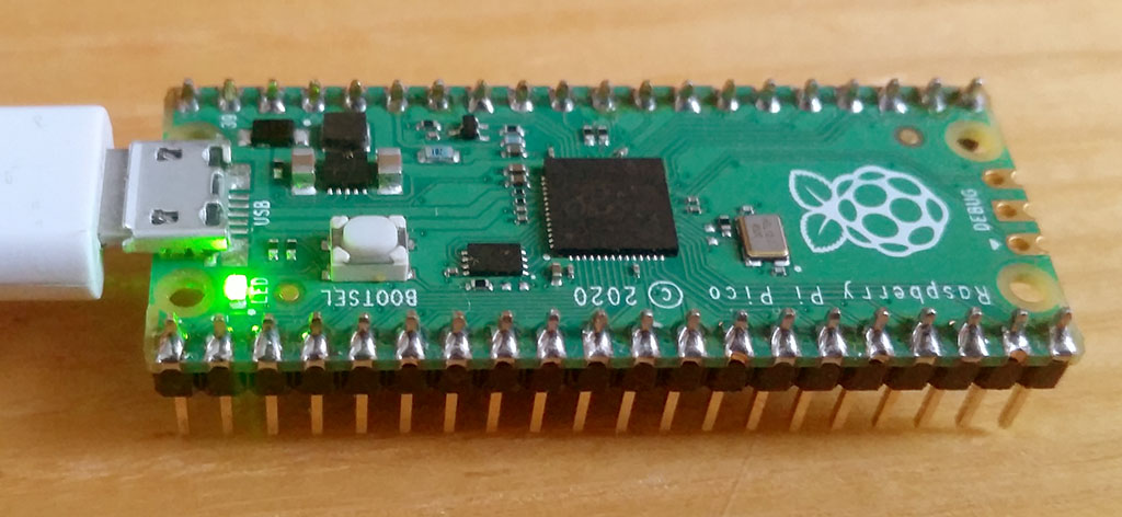
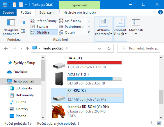
To use the Raspberry Pico for the first time, you need nothing more than an USB cable to connect Pico to the PC. To upload a new program to the Pico, disconnect the USB cable, press and hold the BOOTSEL button on the Pico, connect USB cable, and release the button. A new 127 MB disk, labeled RPI-RP2, appears in the list of disks.
Now you can just drag the new program to this new disk. Of course, the console programmer does not linger with the mouse :-) and uses a simpler method - sending program to the disk with the e.bat command file. For this purpose, it is useful to name the disk uniformly, eg R: (= Raspberry). Renaming is done in computer management - via My Computer / Manage. Or, edit the disk name in the _e1.bat file.
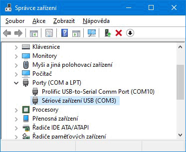
You need console output to try most demos. In the simplest case, you can use the virtual COM port, available via the USB port, used for Pico programming. Most demo programs are ready for this purpose - you will recognize them by the name of the folder ending in *_usb. After loading the program, a new COM port will appear in the device manager, labeled "USB Serial Device". You can open device manager via My Computer / Properties / Device Manager.
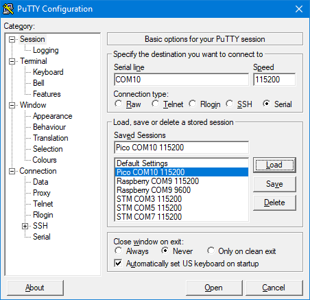
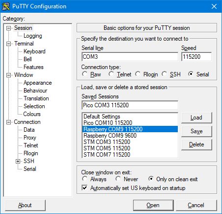
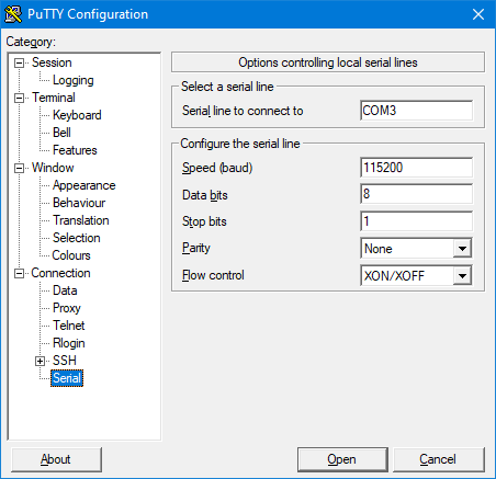
Enter the detected COM port number in the begPuTTY settings. Select baud rate 115200, connection type Serial. In the Connection / Serial setting, set 8 bits, 1 stop bit, no parity, XON/XOFF flow control. In the Terminal settings, enable the "Implicit CR in every LF" option.
The original demo examples allow console output via USB, but not quite. After uploading the demo program, the virtual port is disconnected from the system and then reconnected, which on the one hand takes some time and on the other hand, it takes some time to connect the console program. For begPuTTY, after disconnection, an error window will pop up, which needs to be pressed, and a new connection must be made with the right button on the window with the "Restart Session" option.
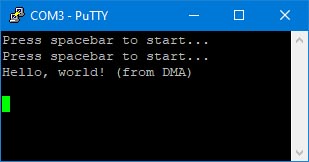
All this means that the message text will run away after start. In such cases, a loop is added to the beginning of the program, waiting for the spacebar to be pressed. The prompt "Press spacebar to start ..." appears in the console window. Of course, this prompt will run after the first run, but you can display it again by pressing a key other than the space bar, such as Enter. The demo program does not start until you press the space bar in the console window.
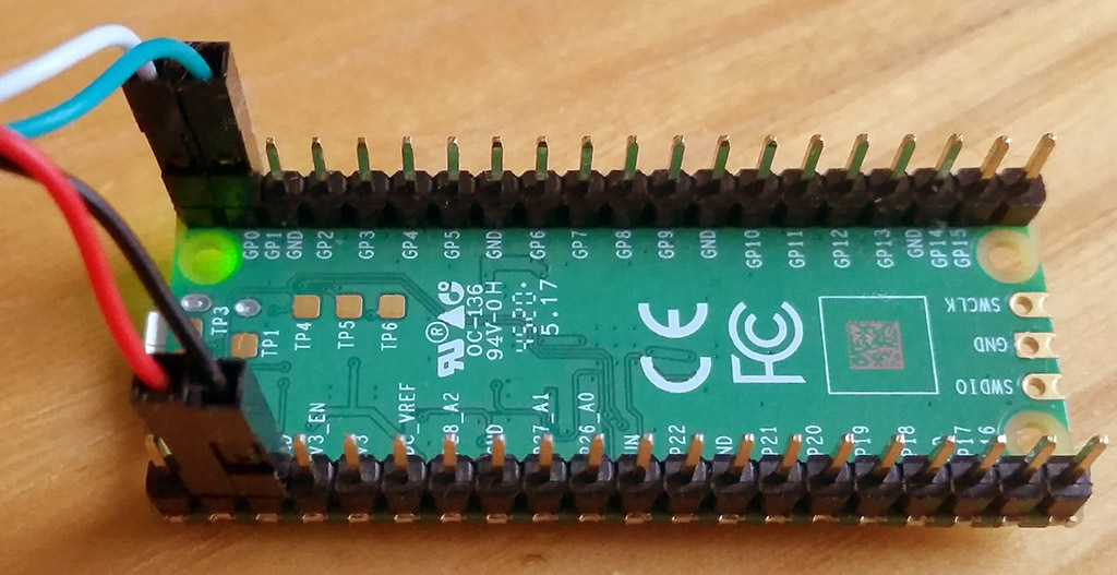
Another option is to connect Pico to the PC via the UART port. By default, UART0 is used for this, which has TX output on pin 1 (GP0) and RX input on pin 2 (GP1).
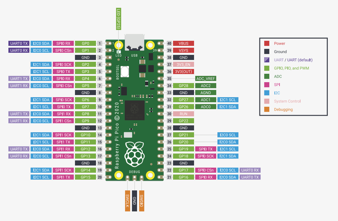
You cannot connect UART0 directly to RS232 of the computer, because it uses 3.3V voltage levels. You must use either RS232 converter or USB converter. A good choice is the USB-UART converter PL2303TA, which can be connected to both +5V TTL pins and +3.3V pins.
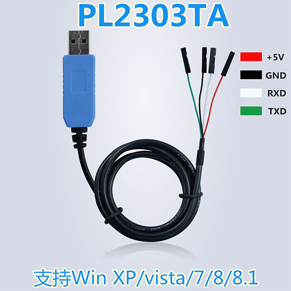
Connect the TX adapter output (green) to pin 2 GP1 UART0_RX, the RX adapter input (white) to pin 1 GP0 UART0_TX. Connect GND (black) to pin 3 GND or 38 GND. If you are going to power the Pico from the converter and not from the USB cable, connect +5V (red) to pin 39 VSYS. According to the documentation, the connection should be made via a diode, but in this case it is not necessary.
After connecting the adapter, a new COM port, "Prolific USB-to-Serial Comm Port", will appear in the device manager. Connect it to begPuTTY in the same way as a USB virtual COM port, except that in the Serial setting, select Flow control = None.
A good combination is the simultaneous connection of both the USB-UART converter and the USB cable. In this case, do not connect the +5V pin (red). By this way you can program Pico and at the same time see the console output without missing the beginning of the text.
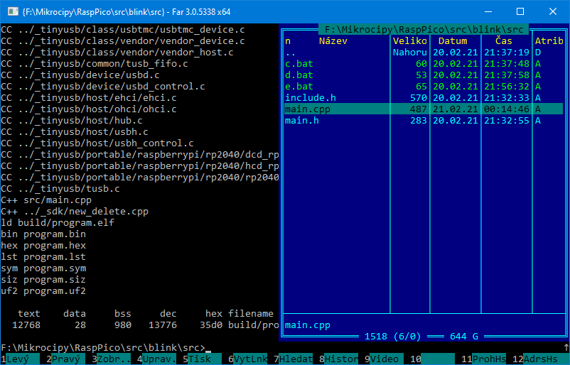
All demo examples in RaspPicoSDK are already prepared pre-compiled (the compiled file is always named program.uf2). Just upload them to Pico by running e.bat (="Export"). If you want to change something in the code, run c.bat (="Compile") to get new compilation. In FAR just press c<Enter>. To clean up compilation, run d.bat (="Delete"). All compiled temporary files will be deleted, leaving only the resulting compiled program.uf2 file.
RaspPicoSDK uses strategy to simplify writing programs, even at the cost of lower translation speed. During compilation, all library files * .c and * .cpp are compiled and linked to the resulting program. The linker ensures that unused pieces of code are not included in the resulting program, so this does not increase the size of the program. Similarly, all *.h files are included in the header files. This approach makes libraries easy to use - you don't have to worry about which library files to add and how to link them together. You just use the required function in the code and you don't care about more.
And yes, of course - the original compilation in Linux is certainly much faster. However, I don't know about you, but I spend a lot more time inventing and writing a program than compiling, so slower compilation doesn't bother me (nowadays fast PCs?) and I prefer that I don't have to worry about anything more than just the code itself.
Of course, during compilation, it is ensured that when editing * .c and * .cpp files, only the modified files are compiled, not the entire project. Therefore, a complete compilation is not required after each code change. However, unlike the original, compilation is not provided depending on the *.h header files. A properly functioning dependency on *.h is a relatively complicated process and does not always work reliably. More than once, when writing programs, I baked myself by looking for errors caused by inaccurate automatic updating of compilations (eg with a variable conditional compilation). Editing *.h files takes significantly less time than editing *.c and *.cpp files, complications with unreliable dependency resolution do not pay off. Just remember this is enough, normally compile quickly with c.bat, and only after significant changes in *.h or with suspicious behavior, first delete before compilation the old compilation with d.bat and then perform the full compilation.
In the basic folder of RaspPicoSDK you will also find the files c_all.bat and d_all.bat - they are used for bulk compilation and deletion of all demo programs. The complete compilation takes about 1 hour.
You will find the project settings in the Makefile for each project. Generally, you can only add additional *.c source files to the CSRC variable and *.cpp files to the SRC variable. If you start from a demo project that is closest to your purpose, you won't have to change other settings. If you are adding *.h header files to the project, add them to the src\include.h file. You include a link to include.h at the beginning of each * .c and * .cpp file.
You will find the following folders in the RaspPicoSDK:
_boot2 - Level 2 bootloaders. A program is loaded into Raspberry Pico in such a way that the internal loader (located in the internal 16 KB BOOTROM) first reads the first 256 bytes from the beginning of the program into RAM at address 0x20041f00 and passes control there. This section is the 2nd level boot loader and is used to set up faster access to Flash memory. The first stage of the boot loader sets a slow but safe approach.
The second stage loader contains a checksum in the last 4 bytes, which is used to identify it. The boot2crc program (translated using MS Visual Studio 2005) is used to calculate the checksum and generate the source code, which will be included in the resulting program. The method of calculating the checksum roughly corresponds to the calculation of CRC32, but differs due to an error in the original code. Therefore, the program does not use the actual CRC32 calculation, but the simulation of original code from the loader.
_exe - elf2uf2 program for exporting a compiled program from elf2 format to uf2 format, and pioasm, a program compiler for PIO. The programs are ready for 64-bit Windows. For a 32-bit system, use libraries from the 32bit folder.
_sdk - SDK library files. The structure is simplified compared to the original SDK. All *.c files are located in one folder and all *.h files are in the include folder.
_tinyusb - TinyUSB library for USB port operation.
_tools - utilities from the MinGW library for handling compilation, such as the "make.exe" program, etc.
_www - the content of this website with a description.
Other folders include demo examples
Folders ending with *_usb use console output to a USB port. Folders ending with *_uart use UART0 console output.
First of all, I recommend trying these 2 basic demo examples:
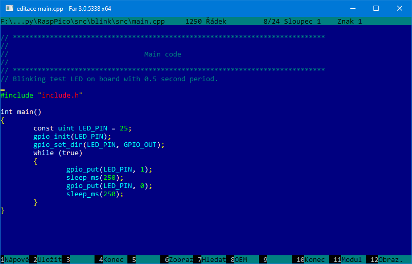
blink ... simple blinking LED on the Pico board
hello_world_usb, hello_world_serial ... repeated printing text "USB: Hello, world!"
Other demo examples:
adc_console_uart, adc_console_usb ... ADC input to console
Menu selected from keyboard:
c0, ... : Select ADC channel n
s : Sample once
S : Sample many
w : Wiggle pins
h : print help
adc_dma_uart, adc_dma_usb ... Capture ADC input using DMA transfer. Capture channel is 0, port GPIO26. If you have VGA board, demo sample (triangle) can be generated using PIO and core 1.
adc_hello_uart, adc_hello_usb ... Repeated measure ADC voltage on pin GPIO26.
adc_joystick_uart, adc_joystick_usb ... Repeated measure joystick position using ADC, X axis on GPIO26, Y axis on GPIO27.
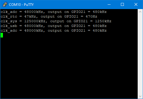
clocks_48MHz_uart ... Measure frequency of on-board clocks with pll and without pll.
clocks_gpout_uart, clocks_gpout_usb ... Output clock signal to GPIO21. Takes different clock sources, divide them by 100 and sends them to GPIO21 as clock signal.
clocks_resus_uart ... Resurection interrupt on system clock fail. Switch pll off. That raises emergency interrupt, which will restore lost system clock.
divider_hello_uart, divider_hello_usb ... Hello hardware divider
dma_control_uart ... Send data to UART using 2 DMAs control blocks.
dma_hello_uart, dma_hello_usb ... Copy data between 2 buffers using DMA.
dma_irq ... Control LED using PWM with PIO and DMA.
flash_cache_uart, flash_cache_usb ... Example of using flash cache hit/access counters
flash_nuke ... clear content of flash. Program will load into SRAM, clear content of Flash, shortly blink LED to indicate all ok and restart USB loader. From now, Pico board will appear empty, as from factory setting.
flash_program_uart ... Program 256-byte page of Flash memory.
flash_ssi_dma_uart, flash_ssi_dma_usb ... Measure transfer speed from Flash to RAM using DMA.
flash_xip_stream_uart, flash_xip_stream_usb ... stream DMAable FIFO
gpio_7segment_uart, gpio_7segment_usb ... Counting 7-segment display. Press button to count down.
gpio_dht_uart, gpio_dht_usb ... Measure temperature and humidity using DHT sensor.
gpio_irq_uart, gpio_irq_usb ... Print events on GPIO 2 (edge fall, edge rise).
i2c_bus_scan_uart, i2c_bus_scan_usb ... Print out a table of I2C slave adresses.
i2c_lcd1602 ... Example code to drive a 16x2 LCD panel via a I2C (3.3V).
i2c_mpu6050_uart, i2c_mpu6050_usb ... Reading MPU6050 MEMS accelerometer and gyroscope
interp_uart, interp_usb ... Texture interpolation
multicore_fifo_uart, multicore_fifo_usb ... Multicore fifo iqrs
multicore_hello_uart, multicore_hello_usb ... Multicore hello
multicore_runner_uart, multicore_runner_usb ... Multicore run functions.
picoboard_blinky ... Blinking Morse text on LED on board.
picoboard_button ... Blink LED if BOOTSEL button is pressed.
pio_addition_uart, pio_addition_usb ... Do some PIO additions
pio_apa102 ... Control RGB LEDs using APA102
pio_blink_uart ... blink LEDs at different frequencies
pio_differ_uart, pio_differ_usb ... Differential serial transmit/receive example
pio_hello ... Blinking LED using PIO
pio_hub75 ... Display an image on a 128x64 HUB75 RGB LED matrix.
pio_i2c_uart, pio_i2c_usb ... Scan an I2C bus.
pio_logic_uart, pio_logic_usb ... PIO logic analyser example
pio_manchester_uart, pio_manchester_usb ... Send and receive Manchester-encoded serial.
pio_pwm_uart, pio_pwm_usb ... Pulse width modulation to fade LED.
pio_spiflash_uart, pio_spiflash_usb ... erase, program and read back SPI serial flash memory
pio_spiloopback_uart, pio_spiloopback_usb ... loopback test with all four CPHA/CPOL combinations.
pio_squarewave ... fast square wave onto a GPIO
pio_st7789 ... display spinning image on ST7789 serial LCD.
pio_uartrx_uart, pio_uartrx_usb ... implement UART receiver
pio_uarttx_uart ... print text on debug UART
pio_ws2812_uart, pio_ws2812_usb ... Example of driving WS2812 addressable RGB LEDs.
pio_ws2812par_uart, pio_ws2812par_usb ... Example of driving WS2812 addressable RGB LEDs.
pwm_duty_uart, pwm_duty_usb ... output PWM and measure duty cycle using another PWM
pwm_hello ... Output PWM signals on pins 0 and 1
pwm_led ... fade LED using PWM
reset_hello_uart, reset_hello_usb ... Perform a hard reset on some peripherals, then bring them back up.
rtc_alarm_uart, rtc_alarm_usb ... Trigger alarm after 5 seconds
rtc_alarmrep_uart, rtc_alarmrep_usb ... Trigger an RTC interrupt once per minute.
rtc_hello_uart, rtc_hello_usb ... set and display RTC clock
spi_bme280_uart, spi_bme280_usb ... Attach a BME280 temperature/humidity/pressure sensor via SPI.
spi_dma_uart, spi_dma_usb ... Use DMA to transfer data both to and from the SPI simultaneously.
spi_flash_uart, spi_flash_usb ... Erase, program and read a serial flash via SPI.
spi_mpu9250_uart, spi_mpu9250_usb ... Attach a MPU9250 accelerometer/gyoscope via SPI.
system_board_uart, system_board_usb ... Read the 64 bit unique ID from external flash, which serves as a unique identifier for the board.
system_dbltap ... Pressing reset quickly twice will reset into USB bootloader
system_write_uart, system_write_usb ... Demonstrate the effects of 8-bit and 16-bit writes on a 32-bit IO register.
timer_hello_uart, timer_hello_usb ... Set callbacks on the system timer, which repeat at regular intervals. Cancel the timer when we're done.
timer_lowlevel_uart, timer_lowlevel_usb ... Example of direct access to the timer hardware.
timer_sampler_uart, timer_sampler_usb ... Sample GPIOs in a timer callback
uart_advanced_uart ... Use some other UART features like RX interrupts, hardware control flow, and data formats other than 8n1.
uart_hello_uart ... Print some text from one of the UART serial ports, without going through stdio.
usb_audio ... Audio headset example from TinyUSB
usb_composite ... Composite HID (mouse + keyboard) example from TinyUSB
usb_generic ... Generic HID device example from TinyUSB
usb_host_uart ... Use USB in host mode to poll an attached HID keyboard (TinyUSB example)
usb_lowlevel_uart ... A USB Bulk loopback implemented with direct access to the USB hardware (no TinyUSB)
watchdog_hello_uart, watchdog_hello_usb ... Set the watchdog timer, and let it expire. Detect the reboot, and halt.
Miroslav Nemecek