Cesky: |


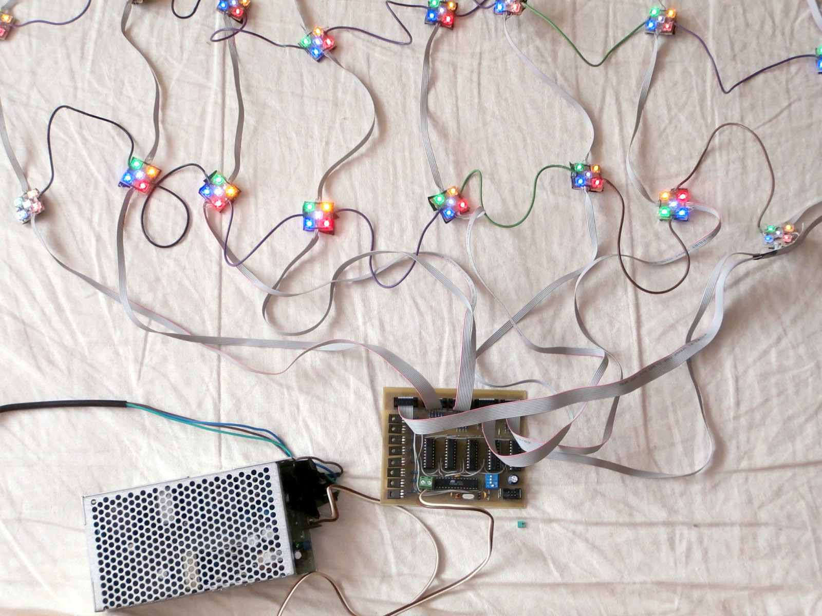
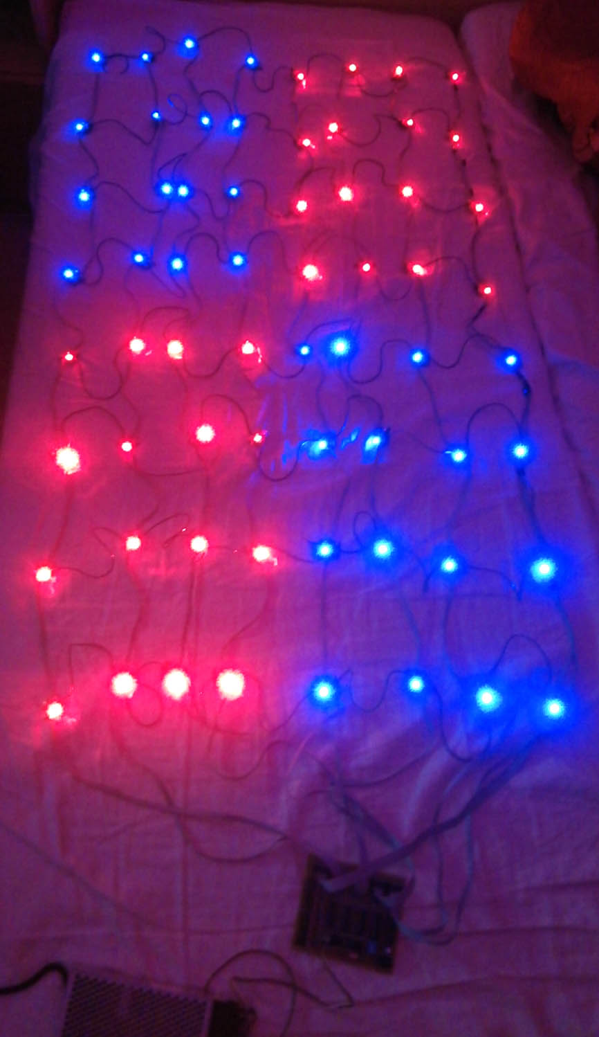
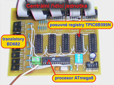
Since I wanted to play around with microchip programming a year ago, I had the idea to create some interesting blinks for my family's Christmas tree. The result was a central control unit with an ATmega8 processor, eight BD682 transistors and five TPIC6B595N shift registers that fed a multiplexed net of 8x8 segments of 5 colored LEDs each.
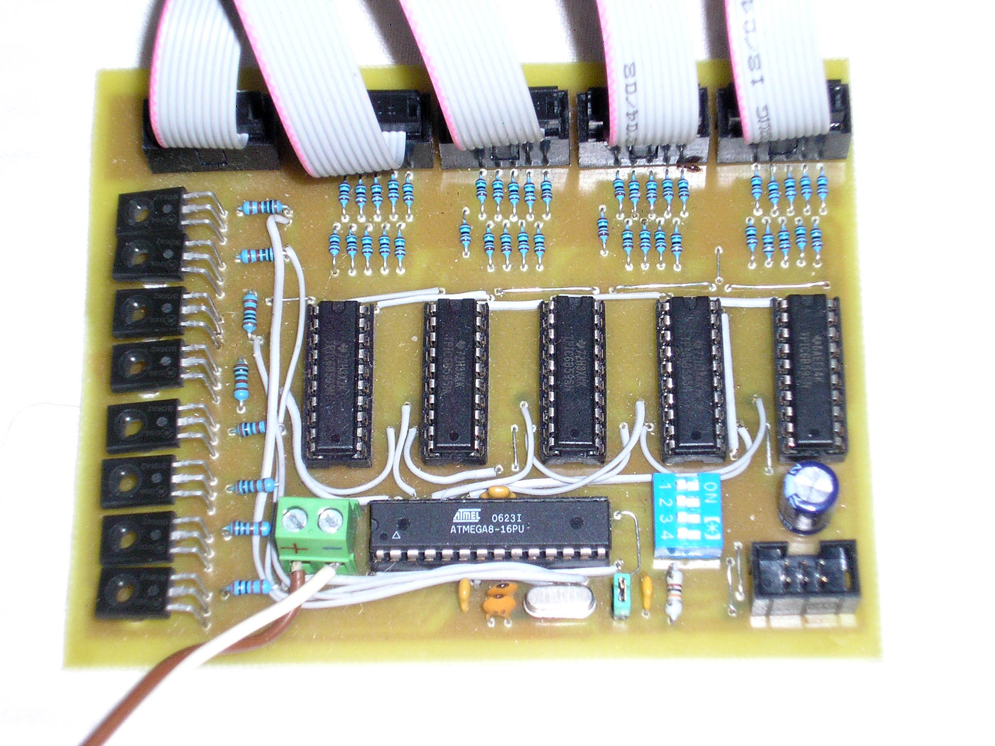
Control Unit: I counted on transistor heat sinks, but it was useless, even at full power they were cold.
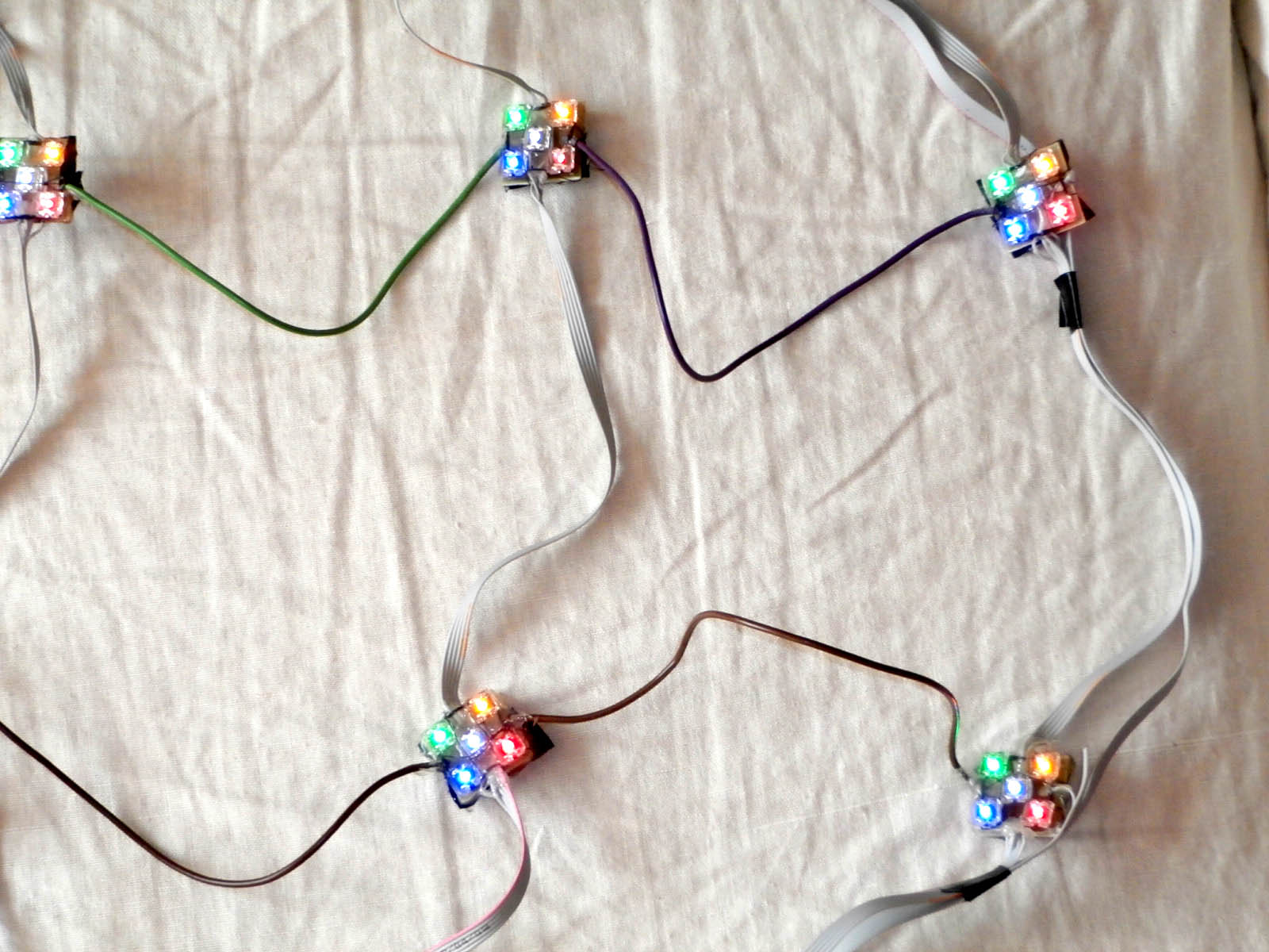
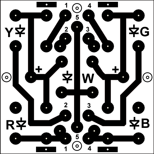
LED Segment: It was necessary to ensure that the flatbed did not short out on the fringes and that the wires did not break by the flatbed. So I glued insulation to the back of the PCB and wrapped everything with thread and sealed it with a hot melt gun. I know it's a lot of fiddling and I believe you can do this better. :-)
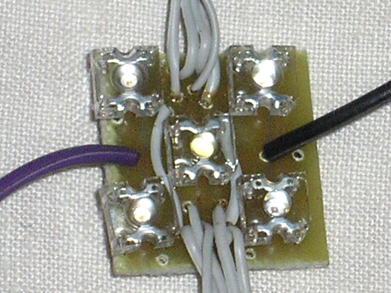
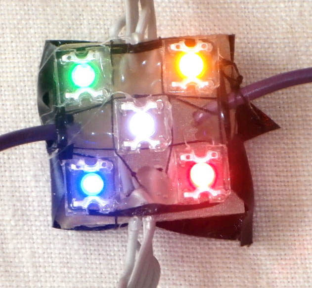
Connecting to the net: The segments are connected in an 8x8 matrix. Horizontally it is 1 wire (multiplex row - it is fed by the outermost 8-core cable) and vertically 5 wires (2 columns are connected to each connector). Note in the previous picture that most of the wires run through the segment using conductive contacts in the LED, but the 2 vertical wires need to be connected with wire jumpers. Choose better wires than I have chosen. They are too thick, inflexible, the netting is then hard to place on the tree (it twists on its own), plus the light colored wires are a bit visible on the tree, especially the grey multi-core ones.
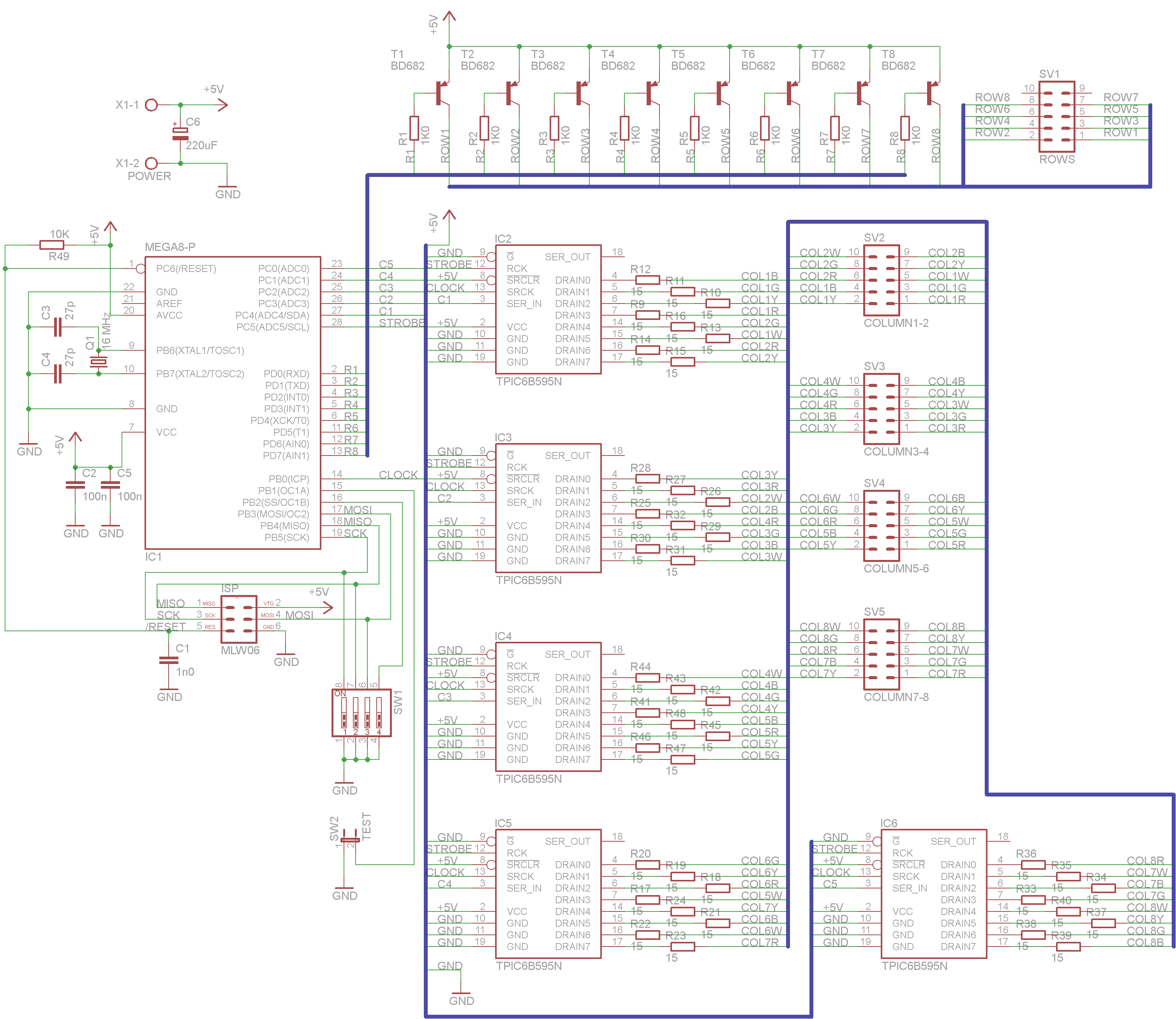
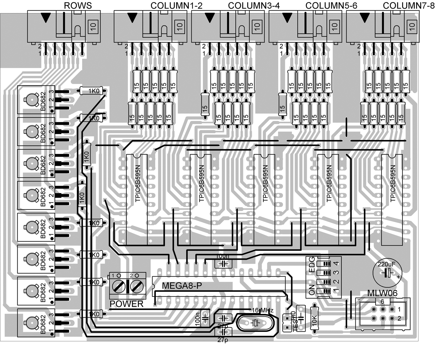
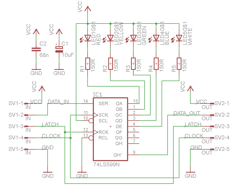
Wiring diagram: The heart of the controller is an ATmega8 processor with a 16 MHz crystal. It directly switches the 8x BD682 row excitation transistors and sends serial data to five TPIC6B595N shift registers, which switch the LED columns. The shift registers have open-collector DMOS switching transistors at the output and are capable of switching current up to 150 mA (500 mA pulsed), so they are well suited for multiplexing. If you replace them with e.g. TPIC6C595N, you need to change the PCB (they have differently placed pins) in addition to the current limitation.
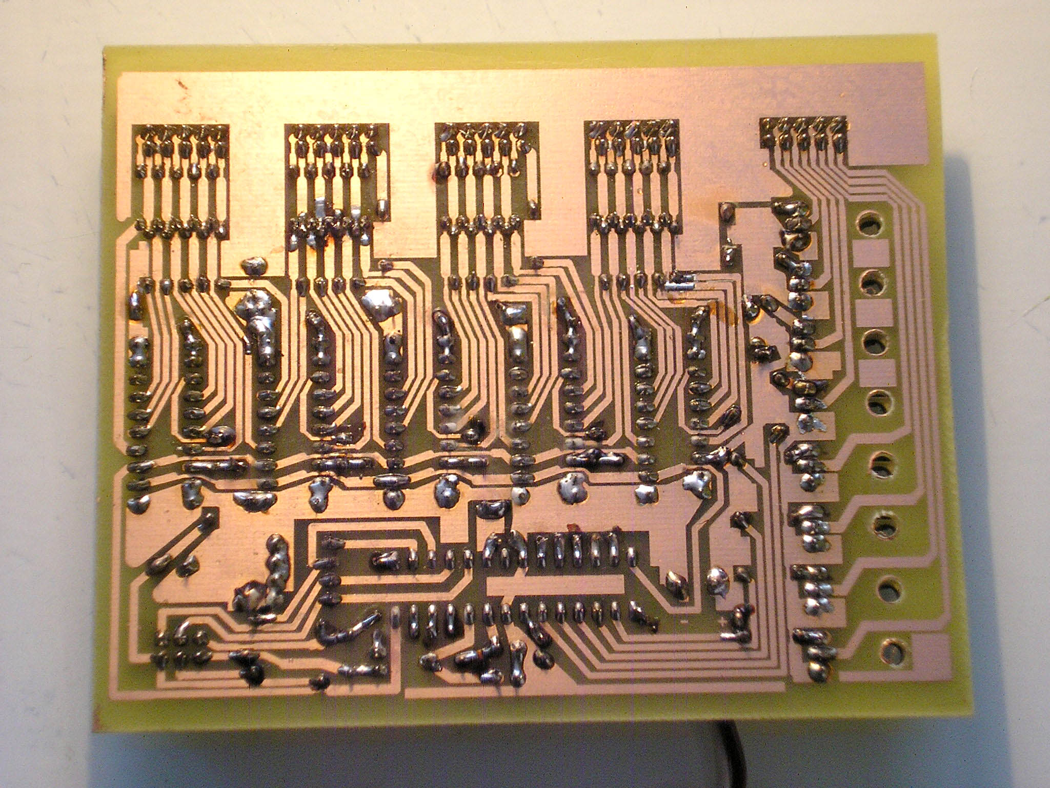
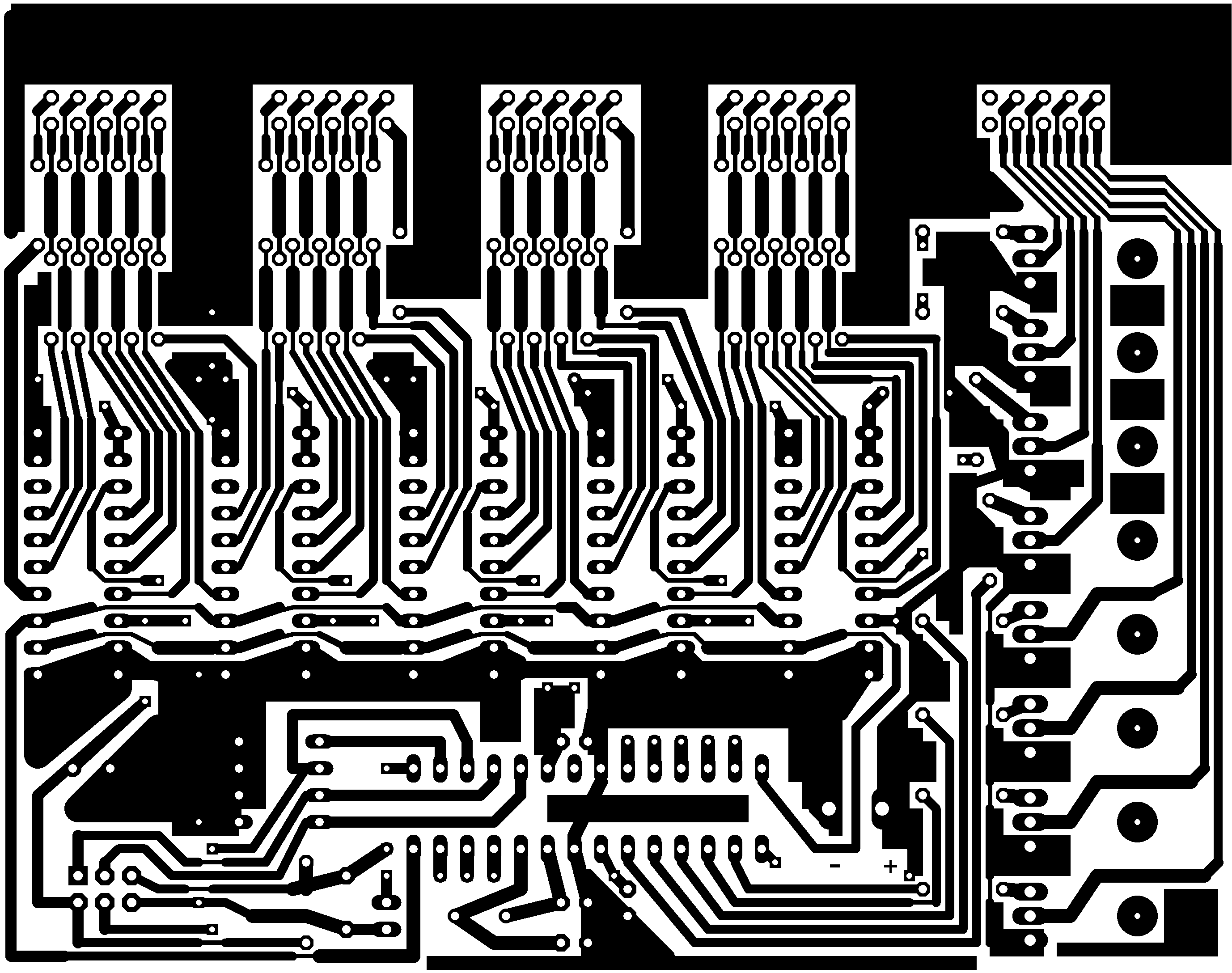
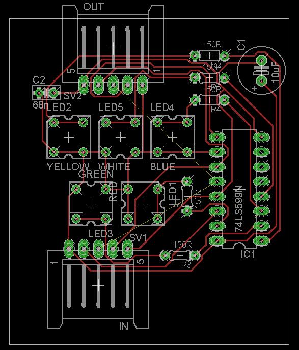
Fitting: I did not avoid some wire jumpers when designing the PCB. But I tried to design in such a way that the jumpers could be replaced by the other side of the double-sided PCB. As I mentioned before, transistors do not heat up and therefore can be placed directly on the PCB (without cooling). The shift registers should be in sockets - it can be assumed that some electrostatics will break through the output and some circuit will need to be replaced (that's why I didn't consider SMD). The resistors on the outputs of the shift registers must be power. I don't have a PCB segment fitting (I didn't do it in Eagle), but you can certainly recognize that.
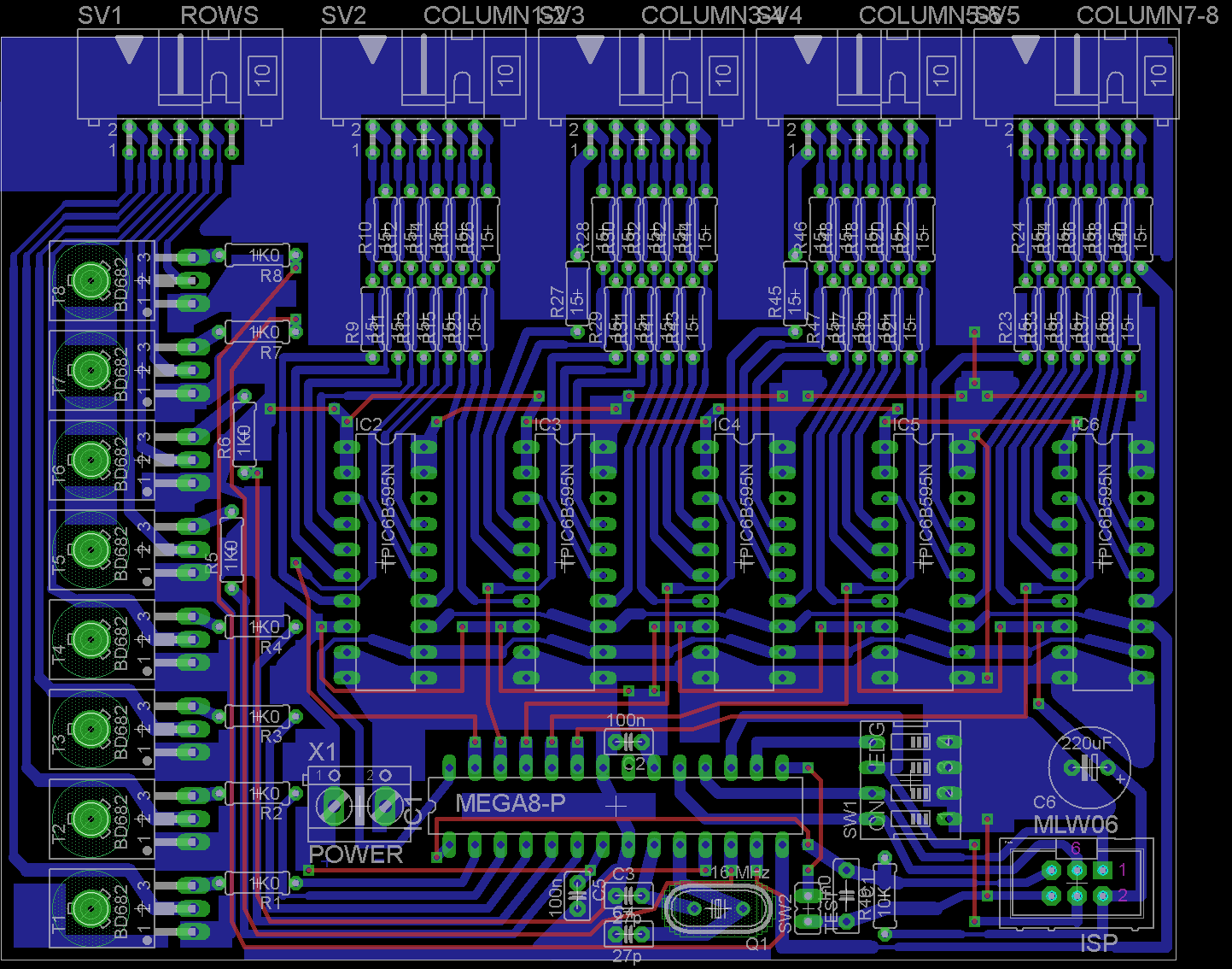
PCB: Because I use the freeware version of Eagle, PCBs are limited to 10x15 cm. Fortunately, this is not directly a limitation of the resulting PCB, but a limitation of the allowed solder spacing. Therefore, the PCB goes even a little "beyond the corner" of the allowed dimension. 64 pieces of the segmented PCB were needed. That's why I printed out an A4 sized template - but I still ended up making it in smaller parts, I wouldn't even light a PCB that big. The holes indicated were where I thought I'd run the wires through to secure them, but that was an impractical idea.

Software: The unit is controlled by a jumper and a DIL switch. The jumper determines whether one of the 14 programs selected on the DIL switch is used or whether the automatic mode of alternating all programs is used. The program contains the resulting "image" in the Img field, which is a sequence of LEDs with a row-column-5 LED organization. Animation routines populate the array with the desired color pattern, and interrupts from the timer then periodically transmit this array to the LEDs with appropriate remapping to serial data. The processor has fuses set high=0xc1, low=0x1f.

Alternative: I will mention the alternative. One of the first suggestions was that instead of a multiplexer, each segment would contain one 595 shift register (the most common type for low current will do) and the segments would be connected in strips with a 5-core cable. I abandoned this option because of the cost (64 shift registers needed - although the number could be halved by sharing 4 LEDs from 2 segments), also because the segment was quite large (it would disturb on the tree) and because I was concerned about jamming the signals (quite high frequency would be needed). But I'm still considering whether that option was interesting after all. For example, with large LED screens, data is also sent serially between segments (a segment is an 8x8x3 LED).
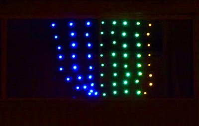
Video - lighting hanging on balcony window:
Download: Source code and schematic (WinAVR-20100110, Eagle freeware)