Cesky: |
Simple DC voltmeter
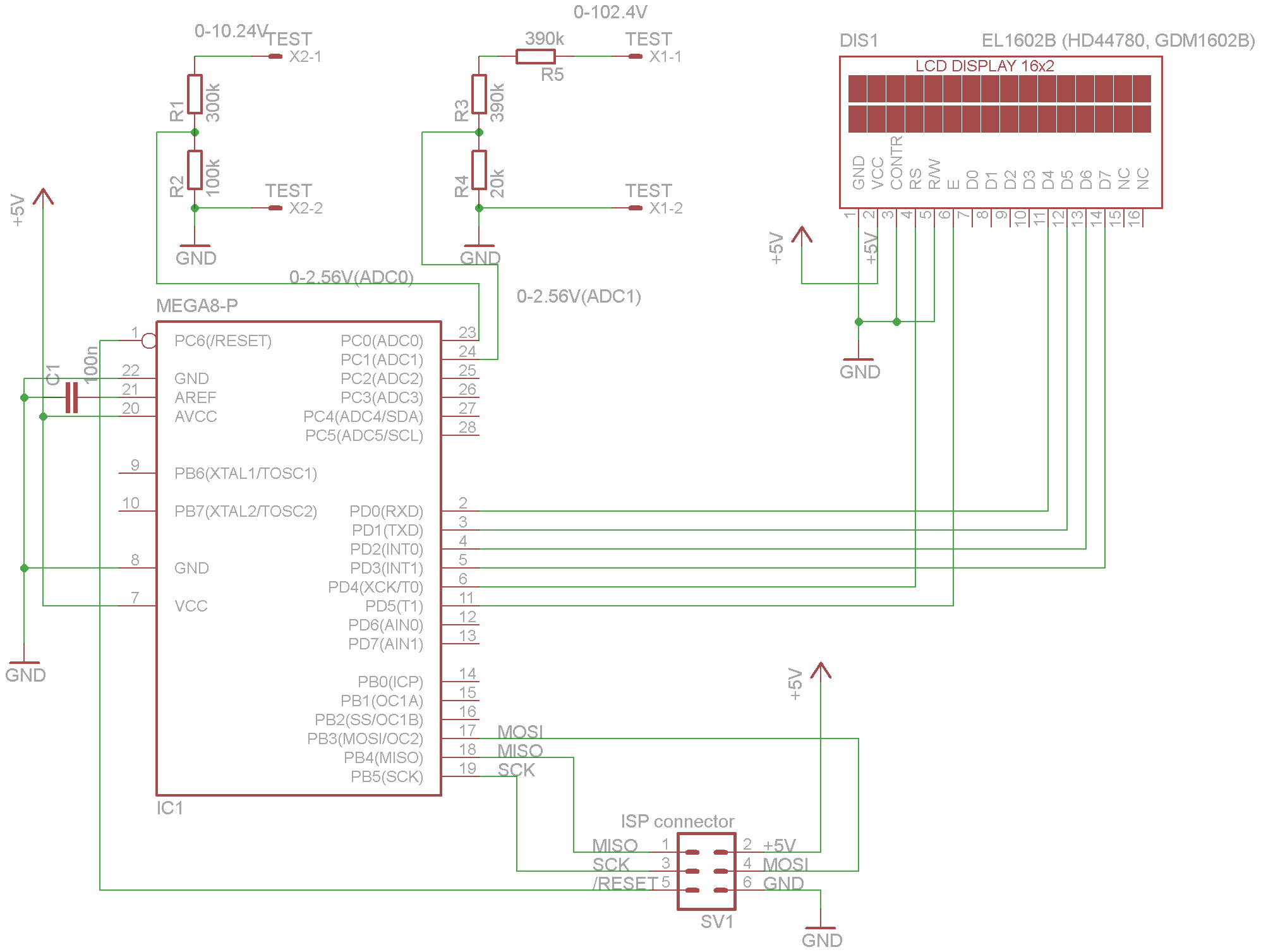
Using an A/D converter, 2 inputs are captured (10V and 100V ranges) and displayed as 2 values on the EL1602B LCD display. There is no PCB, just a schematic, it's just left in the form of a sparrow's nest. :-)
#define	B0	0x1
#define	B1	0x2
#define	B2	0x4
#define	B3	0x8
#define	B4	0x10
#define	B5	0x20
#define	B6	0x40
#define	B7	0x80
typedef signed char s8;
typedef unsigned char u8;
typedef unsigned short u16;
typedef unsigned long int u32;
typedef char BOOL;
#define TRUE 1
#define FALSE 0

/*=============================================================================

            LCD display EL1602B (controller Hitachi HD44780, KS0066)

=============================================================================*/

/*
Running at internal RC 8 MHz

Fuses: high=0xd9, low=0xe4 to 8 MHz (use 0xef on external crystal)

(Normal: high=0xc1, low=0x1f, calibration byte 0xc3)

default: high=0xd9, low=0xe1
*/

/*
http://joshuagalloway.com/lcd.html
http://robo.fe.uni-lj.si/~kamnikr/sola/urac/vaja3_display/How%20to%20control%20HD44780%20display.pdf
http://www.bipom.com/documents/appnotes/LCD%20Interfacing%20using%20HD44780%20Hitachi%20chipset%20compatible%20LCD.pdf

EL1602B-FL-YTS (Y=yellow LED) - japan character set
EL1602B-FL-YBS
EL1602A-FL-YBW
ATM1602B-NL-BBW (B=blue LED)

GDM1602B-FL-YBW

2 rows with 16 rows

Pins and connection:

1 VSS (GND) .... GND (board 1)
2 VDD (+5 V) .... +5V (board 2 with +5V wire)
3 V0 (contrast adjustment)
4 RS (H/L register select signal) ... PC0 (CPU 23, board 3)
5 R/W (H/L Read/Write signal) ... PC1 (CPU 24, board 6)
6 E (H/L Enable signal)	... PC2 (CPU 25, board 4)
7 DB0 (H/L Data bus line) .... PB0 (CPU 12, board 12)
8 DB1 (H/L Data bus line) .... PB1 (CPU 13, board 13)
9 DB2 (H/L Data bus line) .... PB2 (CPU 14, board 14 - last)
10 DB3 (H/L Data bus line) .... PD3 (CPU 1, board 7)
11 DB4 (H/L Data bus line) .... PD4 (CPU 2, board 8)
12 DB5 (H/L Data bus line) .... PD5 (CPU 9, board 9)
13 DB6 (H/L Data bus line) .... PD6 (CPU 10, board 10)
14 DB7 (H/L Data bus line) .... PD7 (CPU 11, board 11)
15 K LED- (0V for back light)
16 A LED+ (+4.2V for back light)

Commands:
00000001 Clear Display and Home the Cursor
0000001* Return Cursor and LCD to Home Position
000001IS Set Cursor Move Direction (I: increment/decrement; S: shift display)
00001DCB Enable Display/Cursor (D: display on, C: cursor on, B: blink on)
0001SR** Move Cursor/Shift Display (S: diplay shift, R: direction right)
001DNF** Set Interface Length (D: 8 bit interface, N: 2 rows, F: big font)
01AAAAAA Move Cursor into CGRAM (A: address)
1AAAAAAA Move Cursor to Display (A: address)

*/

#include <avr/io.h>
#include <util/delay.h>

/* set ENABLE state ON */
#define EN_ON PORTD |= B5

/* set ENABLE state OFF */
#define EN_OFF PORTD &= ~B5

/* set DATA mode */
#define DATA_MODE PORTD |= B4

/* set COMMAND mode */
#define CMD_MODE PORTD &= ~B4

/* output data byte */
#define DataOut(d) { PORTD = (PORTD & 0xf0) | ((d) & 0xf); }

/* write data byte */
void WriteData(unsigned char data)
{
	DATA_MODE;
	DataOut(data>>4);
	EN_ON;
	_delay_us(5);
	EN_OFF;
	_delay_us(5);
	DataOut(data);
	EN_ON;
	_delay_us(5);
	EN_OFF;
	_delay_us(100);
}

/* write command byte, some commands need additional waiting */
void WriteCmd(unsigned char cmd)
{
	CMD_MODE;
	DataOut(cmd>>4);
	EN_ON;
	_delay_us(5);
	EN_OFF;
	_delay_us(5);
	DataOut(cmd);
	EN_ON;
	_delay_us(5);
	EN_OFF;
	_delay_us(100);
}

/* clear display */
void LCD_Clear() { WriteCmd(1); _delay_ms(5); }

/* return to home position */
void LCD_Home() { WriteCmd(2); _delay_ms(5); }

/* set entry mode: right=shift cursor right, shift=shift entire display */
inline void LCD_Entry(BOOL right, BOOL shift)
	{ WriteCmd(4 + (right ? 2 : 0) + (shift ? 1 : 0)); }

/* set display on: disp=display on, cur=cursor on, blink=blinking on */
inline void LCD_DispOn(BOOL disp, BOOL cur, BOOL blink)
	{ WriteCmd(8 + (disp ? 4 : 0) + (cur ? 2 : 0) + (blink ? 1 : 0)); }

/* set cursor shift: shift=cursor shift, right=shift to right */
inline void LCD_Shift(BOOL shift, BOOL right)
	{ WriteCmd(0x10 + (shift ? 8 : 0) + (right ? 4 : 0)); }

/* set CGRAM (character generator) address */
inline void LCD_CGRAM(u8 addr) { WriteCmd(0x40 + addr); }

/* set DDRAM (display data) address */
inline void LCD_DDRAM(u8 addr) { WriteCmd(0x80 + addr); }

void LCD_Init(void)
{
	/* set port to output mode */
	DDRD |= B5+B4+B3+B2+B1+B0;
	EN_OFF;

	/* wait for more than 20 ms for LCD power up */
	_delay_ms(100);

	/* byte synchronisation to new interface */
	CMD_MODE;

	/* byte synchronisation using 8-bit interface */
	DataOut(0x3);
	EN_ON;
	_delay_us(200);
	EN_OFF;
	_delay_ms(5);

	DataOut(0x3);
	EN_ON;
	_delay_us(200);
	EN_OFF;
	_delay_ms(1);

	DataOut(0x3);
	EN_ON;
	_delay_us(200);
	EN_OFF;
	_delay_ms(1);

	/* switch to 4-bit interface */
	DataOut(0x2);
	EN_ON;
	_delay_us(100);
	EN_OFF;
	_delay_ms(5);

	/* set data interface to 8/4 bit, 2 rows, font 5x7 */
	WriteCmd(0x28);
	_delay_ms(5);

	/* display off, cursor off, blinking off */
	LCD_DispOn(FALSE, FALSE, FALSE);

	/* clear display, home cursor */
	LCD_Clear();

	/* auto move cursor right */
	LCD_Entry(TRUE, FALSE);

	/* display on, cursor on, blinking on */
	LCD_DispOn(TRUE, TRUE, TRUE);

	LCD_CGRAM(0);

	WriteData(0x12);
	WriteData(0);
	WriteData(0xf);
	WriteData(0x1b);
	WriteData(0x1b);
	WriteData(0x0f);
	WriteData(3);
	WriteData(0xe);
}


u8 dispbuf[10];

// display number with 1 decimal digit
void dispnum1(u16 num)
{
	s8 i, j;

	i = 0;
	for (;;)
	{
		dispbuf[i] = (u8)((num % 10) + '0');
		num /= 10;
		if ((num == 0) && (i > 0)) break;
		i++;
	}

	j = 3 - i;
	for (; j > 0; j--) WriteData(' ');
	for (; i > 0; i--) WriteData(dispbuf[i]);
	WriteData('.');
	WriteData(dispbuf[i]);
}

// display number with 2 decimal digits
void dispnum2(u16 num)
{
	s8 i, j;

	i = 0;
	for (;;)
	{
		dispbuf[i] = (u8)((num % 10) + '0');
		num /= 10;
		if ((num == 0) && (i > 1)) break;
		i++;
	}

	j = 3 - i;
	for (; j > 0; j--) WriteData(' ');
	for (; i > 1; i--) WriteData(dispbuf[i]);
	WriteData('.');
	WriteData(dispbuf[i]);
	WriteData(dispbuf[i-1]);
}

void dispV()
{
	WriteData('V');
}

#define CNT 1024
#define CNT_BITS 10

int main(void)
{
	u32 sum1, sum2;
	u16 n, adc;

	LCD_Init();

	// ADC: http://www.robotplatform.com/knowledge/ADC/adc_tutorial_4.html

	// enable ADC, set prescaler to 64 (on 8 MHz we need to be lower than 200kHz)
	ADCSRA = (1<<ADEN) | (1<<ADPS2) | (1<<ADPS1) | (1<<ADPS0);

	n = CNT;
	sum1 = 0;
	sum2 = 0;

	while (1)
	{

	// --- measure U1

		// select reference voltage to internal 2.56V, right justify, select ADC input to ADC0
		ADMUX = 0 + (1<<REFS0) + (1<<REFS1);

		// start conversion
		ADCSRA |= (1<<ADSC);

		// wait until conversion completes
		while (ADCSRA & (1<<ADSC));

		// read ADC result
		adc = ADCW;

		// sum value
		sum1 += adc;

	// --- measure U2

		// select reference voltage to internal 2.56V, right justify, select ADC input to ADC1
		ADMUX = 1 + (1<<REFS0) + (1<<REFS1);

		// start conversion
		ADCSRA |= (1<<ADSC);

		// wait until conversion completes
		while (ADCSRA & (1<<ADSC));

		// read ADC result
		adc = ADCW;

		// sum value
		sum2 += adc;

	// --- display result

		n--;
		if (n == 0)
		{
			// display U1
			LCD_DDRAM(0);
			dispnum2((u16)(sum1 >> CNT_BITS));
			dispV();

			LCD_DDRAM(0x40+3);
			WriteData('U');
			WriteData('1');

			// display U2
			LCD_DDRAM(8);
			dispnum1((u16)(sum2 >> CNT_BITS));
			dispV();

			LCD_DDRAM(0x40+8+3);
			WriteData('U');
			WriteData('2');

			// set cursor off
			LCD_DDRAM(0x50);

			// new measure
			n = CNT;
			sum1 = 0;
			sum2 = 0;
		}
	}
}
Download source code and diagram: AVmeter
Miroslav Nemecek